-
Call Now
1800-102-2727

Half Wave Rectifier- Construction and Working, Practice Problems, FAQs

Let me give you an analogy to understand the half wave rectifier. Consider a Two Way road which allows vehicles to travel in both directions. Now if we make it a One Way road then only vehicles moving in one direction will be allowed to travel. Similarly in AC there is positive half cycle and negative half half cycle. By using diodes, we allow only one cycle to pass it to the output side. This is the basic idea of half wave rectification. In this article we will be studying about its construction and working.
Table of Contents
- Half Wave Rectifier
- Parameters of Half Wave Rectifier
- Advantages and Disadvantages of Half Wave Rectifier
- Practice Problems
- FAQs
Half Wave Rectifier
DC voltage is created by half-wave rectifiers from AC voltage. One diode is all that is required for the transformation in a halfwave rectifier circuit. An AC voltage waveform can only travel through one half of a halfwave rectifier, which blocks the other half of the waveform. The most basic type of rectifier is a half-wave rectifier, which just needs one diode to be built into a circuit. This circuit requires three main components:
- Diode
- Transformer
- Resistive Load
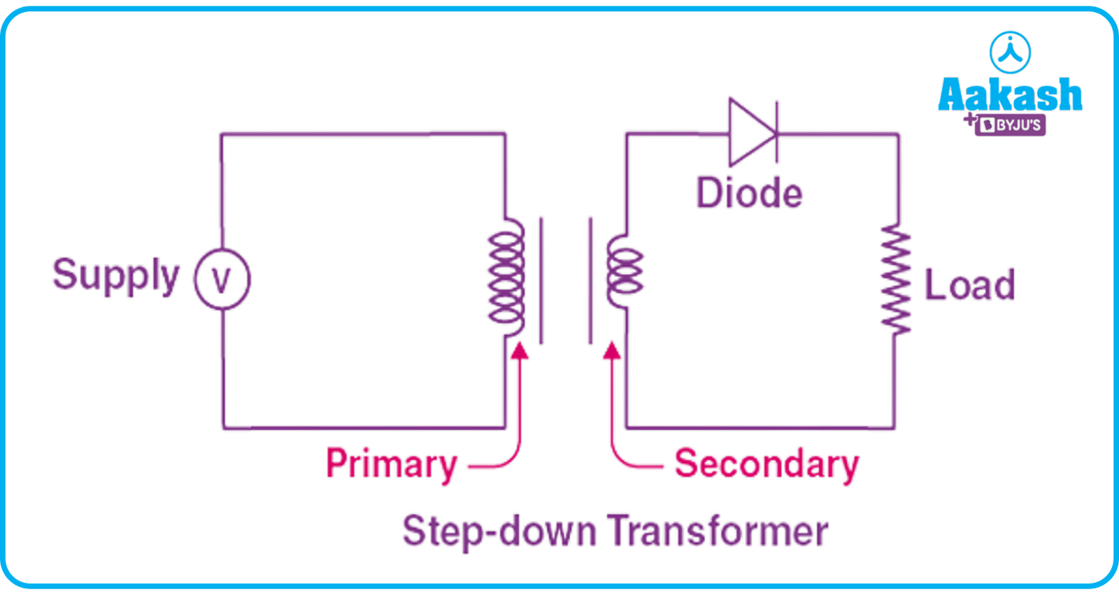
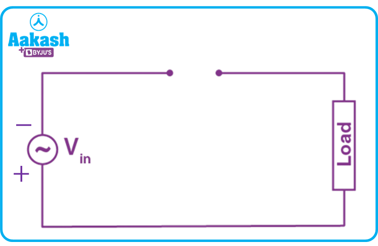
Circuit diagram of the Half Wave rectifier is shown below. It has supply voltage v=Vm sin(t) which is connected to the primary side of the step down transformer. On the secondary side the diode is connected in series with load resistance.
Working of Half Wave Rectifier
- During the positive half cycle, the AC voltage diode is in forward bias. So it allows voltage to pass. So the same voltage is seen across the load resistance.
- During the negative half-cycle of AC voltage, the diode is in reverse bias. So it blocks the negative cycle.
Let's simplify the half-wave circuit for easier understanding by substituting a voltage source for the secondary transformer coils as shown below:
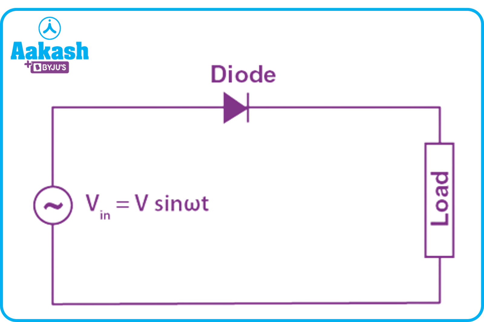
The circuit effectively changes to the form depicted in the picture below for the positive half cycle of the AC source voltage:
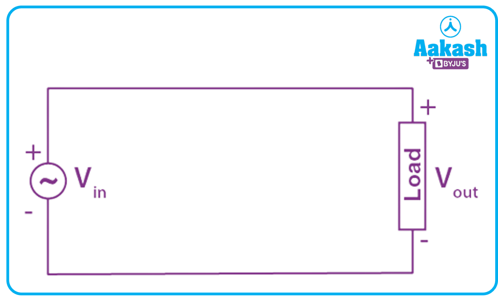
The diode functions as a closed switch when it is forward biased. However, the equivalent circuit changes throughout the AC source voltage's negative half cycle as depicted in the picture below.
A diode functions as an open switch when it is reverse biased. The output voltage is equal to zero since there is no current that can flow to the load.
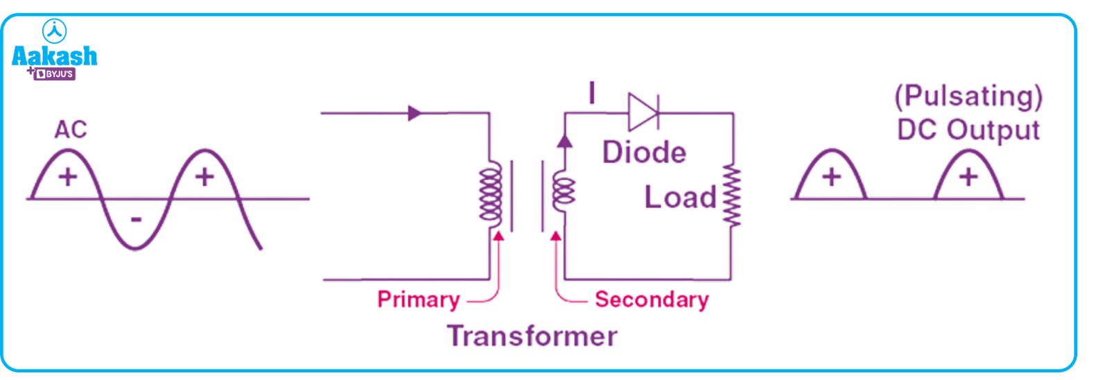
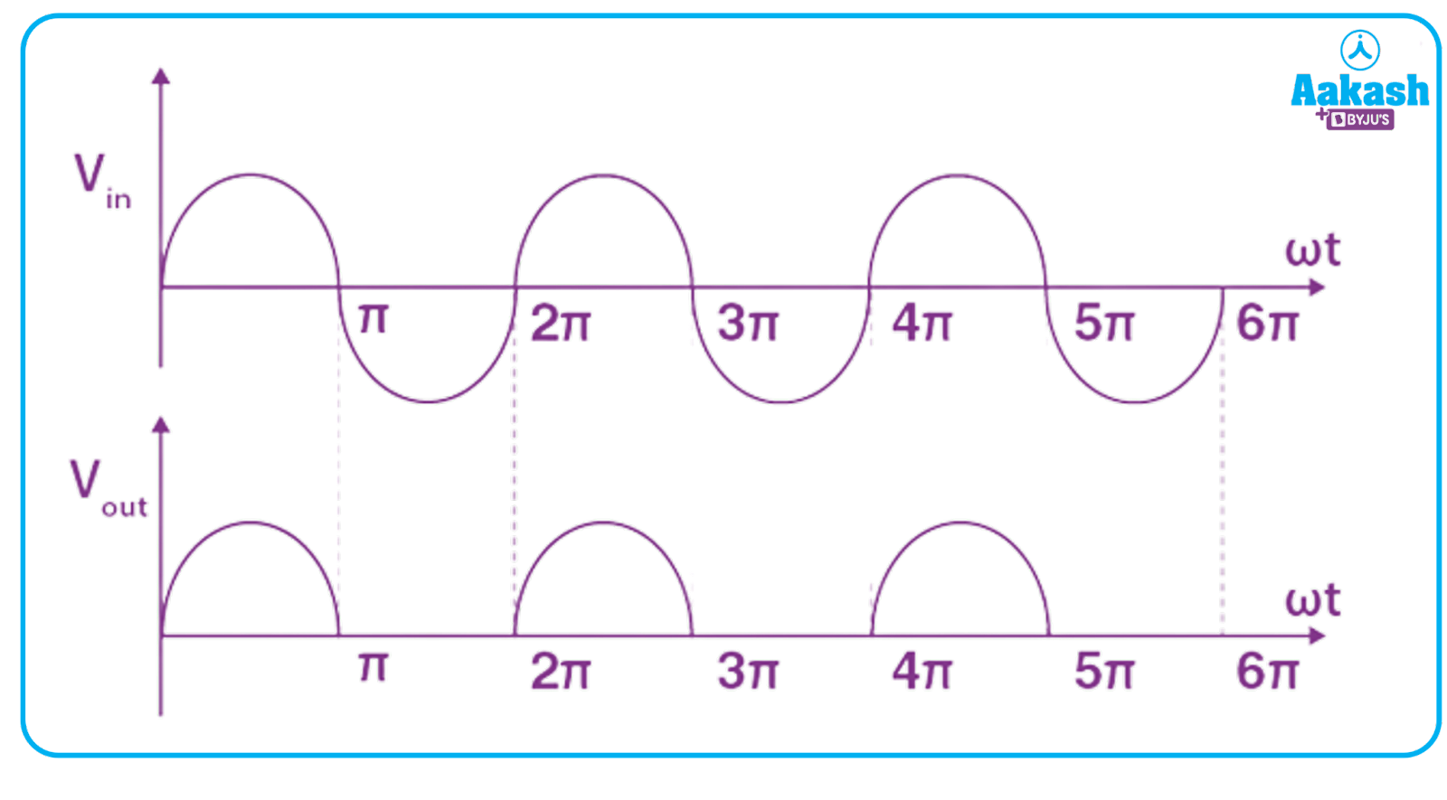
Half Wave Rectifier Waveform
The waveform of a halfwave rectifier both before and after rectification is depicted in the image below.
Parameters of Half Wave Rectifier
Let's calculate the values of different parameters involved in rectification. Assume input applied voltage is v(t)=Vmsin(t). Here Vm is the peak value of voltage and is angular frequency (rad s-1)
- Peak Inverse Voltage (PIV)
The highest voltage a diode can withstand in the reverse-biased direction before it breaks down is called peak inverse voltage. The half-wave rectifier's peak inverse voltage is equal to the peak value of input voltage. PIV=Vm
- DC Output Voltage
Average value of the output voltage waveform is nothing but DC output voltage. Using mathematical expression for average value we can calculate DC output voltage by considering ideal diodes,
- RMS Output Voltage
We can calculate the RMS value using mathematical expression as,
The second term will be zero, as integration of cosine function over the complete period is zero.
- Form Factor
Form factor is defined as the ratio of RMS voltage and Average voltage,
So,
- Peak Factor
Peak factor is the ratio of peak value to RMS value.
- Rectification Efficiency
It is defined as the ratio of DC output power to AC input power. Diodes are ideal and no power loss is taking place because of diodes. So
- Ripple Factor
A ripple is defined as the AC component in the rectified DC output from the rectifier.
Formula for ripple factor is
Advantages and Disadvantages of Half Wave Rectifier
Advantages:
- They serve the aim of signal demodulation.
- They are employed in applications for rectification.
- They serve applications involving signal peaks.
Disadvantages:
- High power loss
- Low output voltage
- The output contains a lot of ripples
Practice Problems
Q. Which rectifier is preferable, the full-wave or the half-wave?
A. Half-wave rectifiers don't perform as well as full-wave rectifiers. A half-wave rectifier only passes one wave, while a full-wave rectifier passes two waves. As a result, more input is sent on to the load. So power loss is higher in a half wave rectifier as compared to a full wave rectifier.
Q. If the input frequency of the source 50 Hz Then what will be the output waveform frequency of a half wave rectifier?
A. Output waveform has the same frequency as that of the input waveform. So output frequency will be 50 Hz.
Q. What is the peak inverse voltage of a half wave rectifier?
A. Peak inverse voltage of a full wave rectifier is equal to the maximum source voltage.
Q. AC source voltage of v(t)=200sin(100t) is rectified using a half wave rectifier. Find PIV, average and RMS output voltage?
A.
FAQs
Q. Where do we use rectifiers?
A. The rectifier's principal function is to convert AC power to DC electricity. Rectifiers are found in practically all electronic equipment's power supplies. The rectifier is generally connected in series with the transformer, a smoothing filter, and potentially a voltage regulator in the power supply.
Q. Which rectifier is more efficient?
A. Full wave rectifier has rectification efficiency of 81 % and for half wave rectifier it is 40.5 %. So a full wave rectifier has better rectification capacity as compared to a half wave rectifier.
Q. Describe the operation of a half-wave rectifier?
A. A PN junction is used in the half wave rectifier circuit to convert the AC source's output into DC. The load resistance and PN junction diodes are linked in series in a half-wave rectifier circuit. Diodes block the negative half cycle. Positive half wave is obtained on the output side.
Q. Where do we use a half wave rectifier?
A. Circuits for firing and pulse generation employ a half-wave rectifier. To provide the required voltage, step up and step down transformers are used with half wave rectifiers.