-
Call Now
1800-102-2727


Bernoulli's Principle - Assumptions, Derivation, Applications, Practice problem and FAQs
We have seen in our daily life that the clouds are generally not stationary, they move from one point to another with different velocities. Then the question arises about why and how they move with different velocities. Basically, the motion of the clouds occurs due to the difference in pressure between the two points. We know the air flows from higher pressure region to lower pressure region therefore if there is a difference in pressure in the atmosphere, the air will flow from higher to lower pressure and hence if the clouds are present in higher pressure region, they will travel towards lower pressure region. Higher the pressure difference, the faster the motion of the clouds. This concept follows a principle called Bernoulli's Principle and we will know about it in this topic.
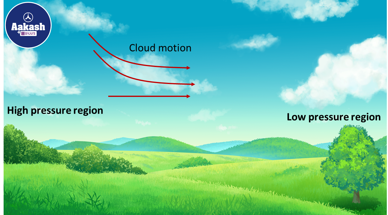
Table of content
- What is Bernoulli’s Theorem? (The "Simple" Version)
- Assumptions for fluid dynamics
- Continuity equation
- Bernoulli's Principle
- Derivation of Bernoulli's formula
- Application of Bernoulli's Principle
- Practice problems
- FAQs
What is Bernoulli’s Theorem? (The "Simple" Version)
Imagine you are spraying water from a garden hose. If you put your thumb over the opening to make the water go faster, the pressure right at that opening actually drops.
In the simplest terms: When the speed of a flowing fluid (like air or water) increases, the pressure within that fluid decreases.
Swiss mathematician Daniel Bernoulli discovered this in the 18th century. He realized that for a fluid to stay "balanced" in terms of energy, if it gains speed (kinetic energy), it must lose some pressure (pressure energy).
Assumptions for fluid dynamics
1) Ideal fluid flow:
a) The fluid is incompressible. It means that the density of the fluid will not change during the flow.
b) The fluid is non-viscous i.e. there is no friction between the fluid layers.
c) The fluid is irrotational or the angular velocity is zero.
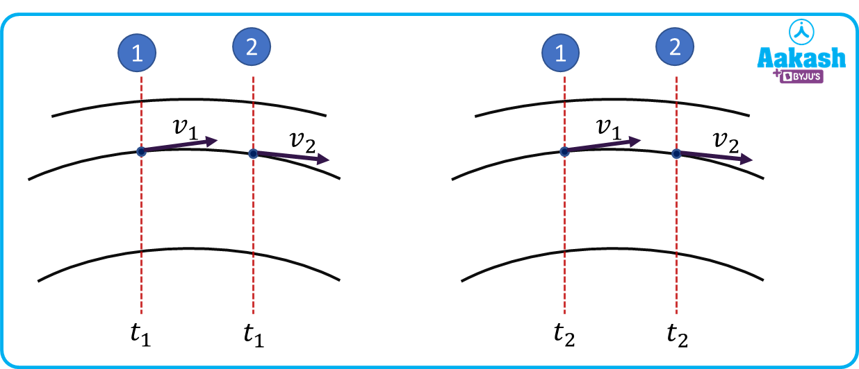
2) The flow is a steady or streamline flow. Steady or streamline flow means that the velocity of a fluid particle at a point will be constant with time and any particle follows the path of the previous particle.
Continuity equation
The continuity equation is based on the principle of continuity which states that,
“The mass of the fluid at a certain section will be the same with the time.”
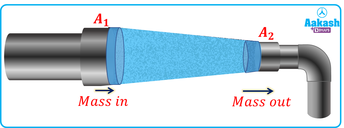
The continuity equation is derived on the basis of conservation of mass. It means that the mass entered at the inlet of a pipe should be equal to the mass leaving out at the exit of the pipe. Or we can say that the mass flow rate from a pipe is constant.
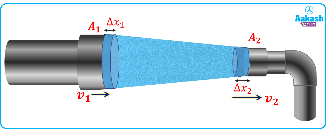
Now Consider a pipe section having area at inlet as A1, mass is m1 and having area at outlet as A2, mass m2. Let the distance covered by the fluid at inlet is and distance covered by the fluid at the outlet is . Since the fluid is incompressible therefore the density of the fluid will not change and let the density of the fluid is .
Since, mass = density volume
Then the mass flow rate at the inlet is,
Let the velocity of the fluid at the inlet and at the outlet is v1 and v2 respectively. Then,
From equation (i),
Similarly at outlet, the mass flow rate will be,
Now from the conservation of mass, there is no change in mass with the time in the pipe section, therefore
Change in mass with time = Mass flow rate at inlet - Mass flow rate at outlet =0

Or we can write as,
This is also known as the volume flow rate of the fluid.
Bernoulli's Principle
The principle of Bernoulli is based on the principle of conservation of energy. It states that,
“The total energy in a moving fluid that involves potential energy due to height, pressure energy due to fluid pressure, and the kinetic energy due to motion of the fluid remains constant.”
Mathematically it is written as,
In the above equation, the pressure energy, the kinetic energy and the potential energy are in per unit volume, where,
P= Pressure exerted on the fluid
= Density of the fluid
v= Velocity of the fluid
h= Elevation
Bernoulli’s principle is stated by Daniel Bernoulli and he concluded that if we take the same elevations for the inlet and the outlet then as the pressure will increase of a moving fluid, the velocity will decrease to balance the energy.
Since Bernoulli formulated only the principle but it was derived by another person Leonhard Euler in 1752.
Derivation of Bernoulli’s principle
Bernoulli’s principle is basically based on the conservation of energy of the fluid.
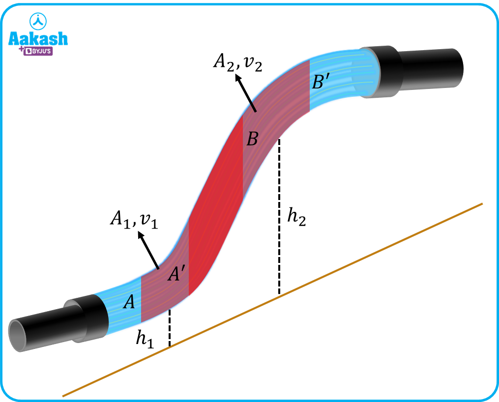
Consider a steady or streamlined flow in a tube having a variable diameter and an ideal fluid is flowing through it as shown below.

Now consider an element AB of the flowing fluid which is moved to A'B' in a time interval of . As seen from the above figure, the region A'B is common for both AB and A'B’, then it can be considered as an unmoved section of the fluid. Hence we can consider that only AA' is moved to BB'. Now consider A1, v1 and h1 is the area, velocity and elevation from the datum line for AA' and A2, v2 and h2 is the area, velocity and elevation from the datum line for BB'.
Now consider P1 and P2 are the pressure exerted on AA' and BB' as shown in figure, then,
Pressure force on AA'=P1A1
Pressure force on BB'=P2A2

Now from the conservation of mass,
Mass in A'B = Mass in= Mass out
Now, from the work-energy theorem, the change in kinetic energy will be balanced by work done by pressure exerted on the fluid and work done by gravity due to elevation.
Change in kinetic energy
Work done by pressure (Wpress)+ Work done gravity due to elevation (Wg)
Now work done by pressure on element AA'=P1A1(v1t)
And work done by pressure on element BB'=P2A2(v2t)
Then net work done by the pressure will be
The change in kinetic energy is,
And the work done by gravity due to elevation is.
Then from the work-energy theorem,
Now from equation (ii),
After resolving we get,
Or
Hence the above equation is known as the Bernoulli’s formula for per unit volume of the fluid.
Quick Comparison: Continuity Equation vs. Bernoulli’s
Students often confuse these two.
• Continuity Equation (A1 v1=A2v2): Tells us that if a pipe gets narrower, the fluid must move faster to keep the mass flow constant.
• Bernoulli’s Theorem: Tells us that because the fluid is moving faster (thanks to the narrow pipe), its internal pressure must drop.
Application of Bernoulli’s principle
There are many applications present in which we can use Bernoulli’s principle to analyze the properties of the flow. Some examples are described below;
- Dynamic lift: The dynamic lift is the upward force generated by the fluid on the body when either the fluid is in motion and the body is stationary or the fluid is stationary and the body is in motion. The dynamic lift can be understood by the use of Bernoulli’s principle.
Flow over a cylinder: When the cylinder is stationary and fluid is flowing over it then no lift will be generated as the flow over the stationary cylinder is symmetric for the upper and lower portion of the cylinder hence no pressure difference is created on the upper and lower portion of the cylinder (As shown). Now if we rotate the cylinder rotating (let’s say in clockwise direction) about its axis, the fluid layers will be dragged along the spinning cylinder and on the upper side of the cylinder, the velocity of the fluid will be increased to cross the cylinder and hence from the Bernoulli's principle we can say that the pressure will be decreased on the upper portion of the cylinder. This will create an upward force on the rotating cylinder which is known as the lift.
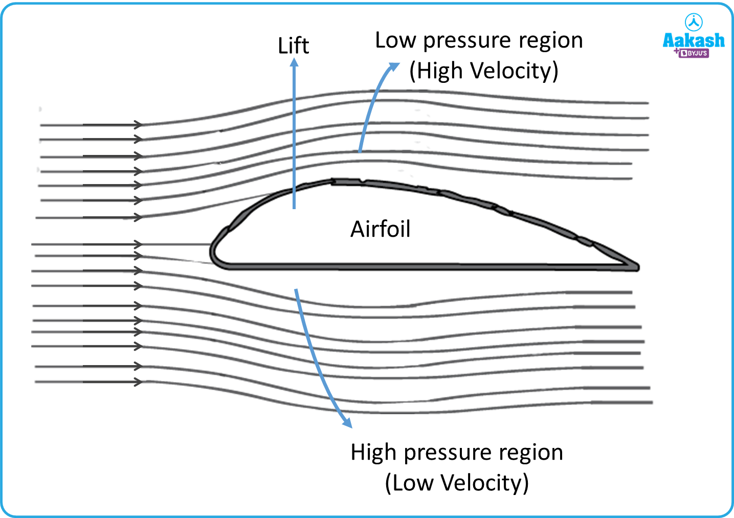
Lift generation on an airfoil: Consider an asymmetrical airfoil in a flowing fluid as shown. As we can see in the figure, the fluid layers passing over the upper portion of the airfoil has to cover a larger distance due to its curvature hence the fluid has to travel with a higher velocity compared to the fluid layers flowing in the lower portion of the airfoil. Now according to Bernoulli’s principle, this relative velocity over the airfoil will create the pressure difference between the upper and lower portions of the airfoil. The pressure will be reduced in the upper portion due to the high velocity of the flow and pressure will be high at the lower portion due to the low velocity of the flow. This pressure difference will create an upward force and the airfoil lifts and this is how an aeroplane flies in the air.
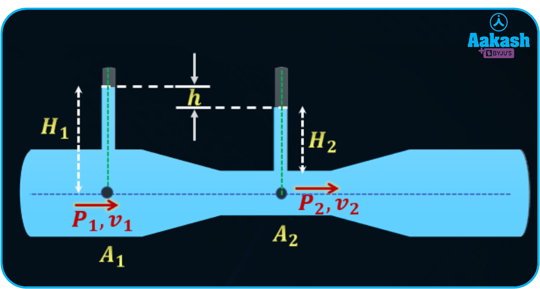
- Venturimeter: A venturimeter is a device to calculate the flow rate of the fluid passing through a tube. It works on Bernoulli’s principle. The device has three parts, the converging part, throat, and diverging part. Two small diameter tubes are placed before the converging part and at the throat to measure the pressure heads as shown,

Let the pressure, velocity, cross-sectional area, and the height of the liquid above the reference level at section 1 are P1, v1, A1 and H1 and similarly the pressure, velocity, cross-sectional area, and the height of the liquid above the reference level at section 2 are P2, v2, A2 and H2. Now applying Bernoulli’s principle between section 1 and 2.
Then the pressure head,
From the continuity equation (A1v1=A2v2), we can calculate the velocity at section 1 as,
Hence the volume flow rate is calculated as,
Practice problems
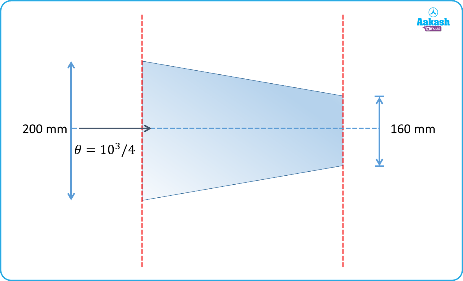
1. Water flows in a converging section with a discharge of 20 m3/h. If the diameter at inlet is 200 mm and diameter at outlet is 160 mm then find the velocities at inlet and at the outlet.
A. Given, Discharge or volume flow rate,
Diameter at inlet
Diameter at outlet
Let the velocities at inlet and outlet are v1 and v2 respectively.
Then from the continuity equation,
The velocity at the inlet will be,
v1=0.176 m/s=0.18 m/s
The velocity at the outlet will be,
v2=0.276 m/s=0.28 m/s
2. A fluid is flowing through a converging pipe of diameter 100 mm and 40 mm. If the pressure drop across the pipe is 10 N/m2, then find the discharge through it. The density of the fluid is 1.25103 kg/m3.
A. Given, Diameter at inlet d1=100 mm=10010-3 m
Diameter at outlet d2=40 mm=40x10-3 m
Pressure drop across the pipe, P1-P2=10 N/m2
Density of the fluid, =1.25x10³ kg/m3
From the continuity equation,
A1v1=A2v2
Now from the Bernoulli’s equation,
Now from equation (i)
After solving, we get
This is the velocity at the outlet of the pipe.
The discharge will be,
3. A diverging duct having diameters of 100 mm and 200 mm is placed inclined as shown in figure. The density of the fluid flowing through it is 1000 kg/m3. The velocity of the liquid at point A is 1 m/s. Calculate the value of difference in pressure across point A and B. (g=10 m/s2)
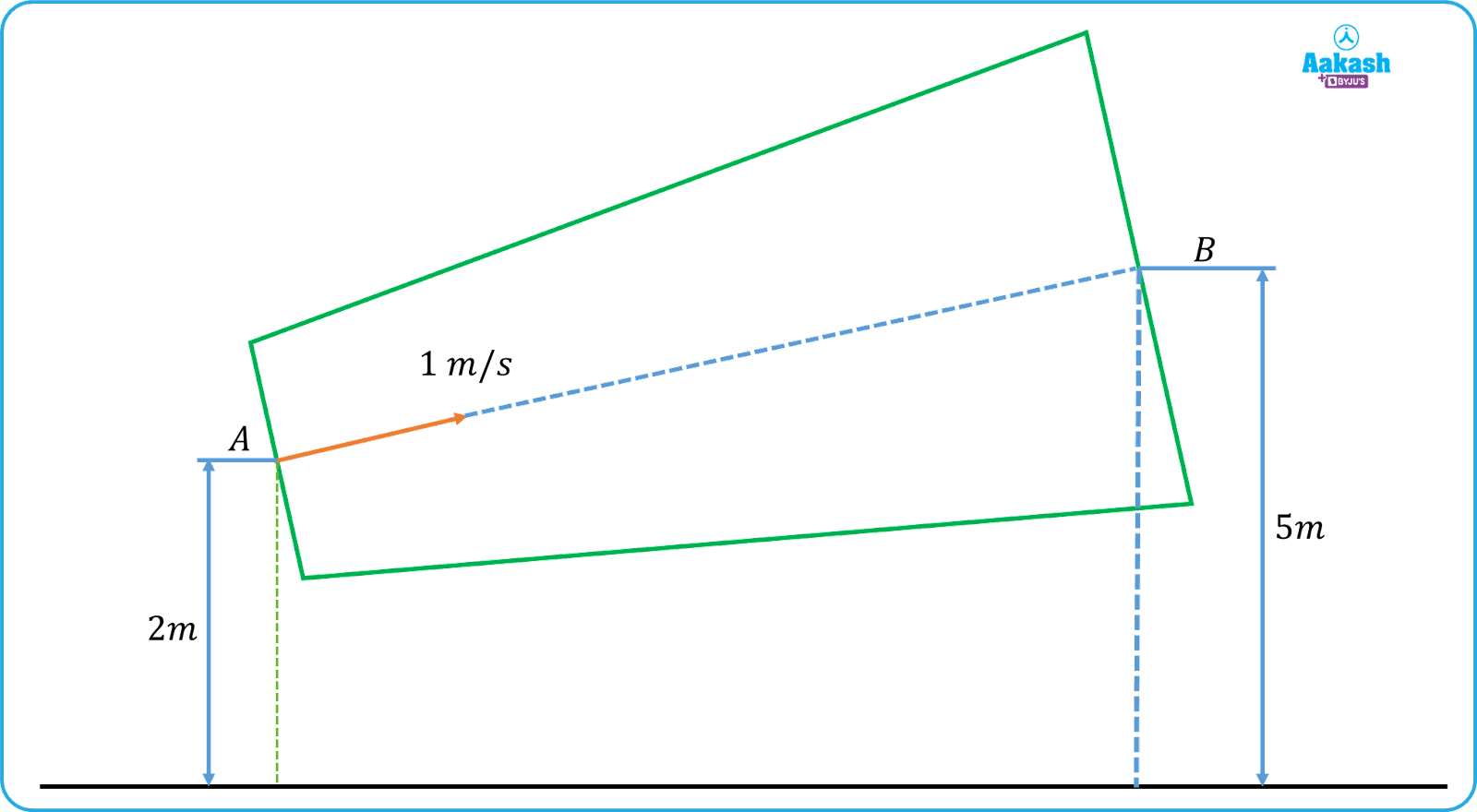
A. Given, Diameter at inlet dA=100 mm=100x10-3 m
Diameter at outlet dB=200 mm=200x10-3 m
Density of the fluid,
Velocity of the fluid at section
Height of section
Height of section

From continuity equation,
Then,
Now applying the Bernoulli’s equation between section A and B,
4. Water is flowing through a venturimeter as shown. The height of the water column at point 1 is 5 cm and height of the water column at point 2 is 3 cm. The area of cross-sections of the venturimeter at 1 and 2 are 5 cm2 and 2 cm2 respectively. Then find the discharge.
(g=10 m/s2).
A. Given, cross-sectional area at 1, A1=5 cm2=5x10⁻⁴ m2
Cross-sectional area at 2, A2=2 cm2=2x10⁻⁴ m2
Height of the water column at point 1, H1=5 cm=5x10⁻² m
Height of the water column at point 2, H2=3 cm=3x10⁻² m
The difference between heights of the water column is,
h=H1-H2=(5-3) cm=2x10⁻² m
Now the discharge through venturimeter is given by,
Q=0.13810-3 m3/s
FAQs
1. Why is the roof of a tin-shed detached from it during a storm if it is not tightened well?
A. During the storm the wind speeds are very high therefore the pressure will be less as compared to the pressure inside the tin-shed therefore there will be an upward force applying on the tin-shed by which the storm tries to pull the tin-shed from the ground and if the roof of the tin-shed is not tightened well then it can detach from the tin-shed.
2. Write the assumptions for Bernoulli’s principle.
A. To define Bernoulli’s principle, it is assumed that,
i) The flow is ideal, it means that the flow is irrotational, non-viscous and incompressible.
ii) The flow is steady or streamline flow
3. Define steady flow.
A. When flow of a fluid occurs in such a way that, at a point in the flow the velocity of the flow remains constant with respect to time then the flow is a steady flow. The velocity of the flow can be different at different points in the flow but it will be constant at those points with time always.
4. If we stand on a railway platform near to the track and a non-stop train passes from that platform then why do we feel a pulling force towards the train when it passes?
A. The explanation is based on Bernoulli’s principle. When the train passes from the platform, it creates a low pressure region near to it as the it is moving with a high velocity and there is atmospheric pressure around us but if we are standing near to track of the platform the difference between pressure becomes high and when the train passes we feel a pulling force towards the train i.e we are being pulled towards the low pressure region from high pressure region.
5. How does Bernoulli’s Principle explain how an aeroplane flies?
An aeroplane wing is curved so air moves faster over the top than the bottom. According to the Bernoulli effect, this higher speed creates lower pressure on top and higher pressure below, resulting in an upward lift force.
6. Why does a spinning cricket ball "swing" in the air?
When a ball spins, it creates a difference in air velocity on either side. This velocity difference leads to a pressure imbalance based on Bernoulli’s theorem, causing the ball to curve or "swing" away from its straight path.