-
Call Now
1800-102-2727

Impedance in series LCR circuit, impedance triangle, solved examples, FAQs

Let me give you an analogy to understand the impedance. There are speed breakers on the road to slow down the speed of vehicles. They act as an obstacle while driving on the road. Similarly impedance is an obstruction to flow of electrons in an AC circuit. In an electric circuit if there is inductor, capacitor and resistor in series connection we call it a series LCR circuit. This series LCR circuit offers a combined impedance to flow of electrons. So in this article we will be analysing series LCR circuits in detail.
Table of Contents
- Series LCR circuit
- Impedance in series LCR circuit
- Impedance Triangle
- Impedance Vs Frequency
- Solved Examples
- FAQs
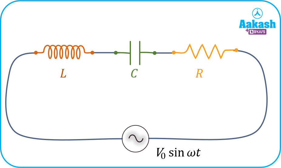
Series LCR circuit
Let’s consider the series LCR circuit as shown below.


 AC voltage is supplied to the circuit.
The current passing through all three elements L, C, R is the same so we call it a series LCR circuit.
Assume that the peak current in the given LCR circuit is 
Since the phase difference between current and voltage for a purely resistive circuit is zero, there will not be any phase difference between peak voltage across the resistance ( ) and the peak current in the circuit (). Thus, phasor representing and are in the same line.
The phase difference between current and voltage for a purely inductive circuit is ( ) ⇒ The phase difference between peak voltage across the inductor (
 ) and the peak current in the circuit () is also the same. Thus, phasor representing lags behind by an angle
  .
.
The phase difference between current and voltage for a purely capacitive circuit is ⇒ The phase difference between peak voltage across the capacitor ( ) and the peak current in the circuit () is also the same. Thus, phasor representing is ahead of by an angle .
Now we can draw the phasor diagram as shown below.

With reference to above phase diagram, since the voltage across each electrical component are treated as vectors, the net voltage in the series LCR circuit will be,

Assuming  , we can say that the net sum of the peak voltage of these two terms will be
  , as shown in the phasor diagram.
Therefore, the peak voltage of the net voltage in the circuit will lag behind the current by an angle 𝜙 as shown in the figure.
Therefore, the current in the circuit, 
Impedance in series LCR circuit
Let’s find the impedance of the series LCR circuit using the phasor diagram.
Net voltage is the phasor sum of three voltages across each element i.e. L, C, R. So we can write it as,
Using Pythagoras theorem we can write,
 ………….(1)
the peak voltage across resistor, inductor and the capacitor can respectively be written as follows:


Where,


According to Ohm’s Law we can write,
 ……….(2)
Using equation (1) we can write,
Put values of  and
and  in above equation,

By solving we get,

Therefore,

SI unit of impedance is 
Impedance Triangle
This is the LCR series circuit we are analysing.
For this LCR series circuit we have drawn the phasor diagram as shown below:
From this we can write,

We know,
So, 
Therefore the expression for the current become,

We can draw the impedance triangle as shown:

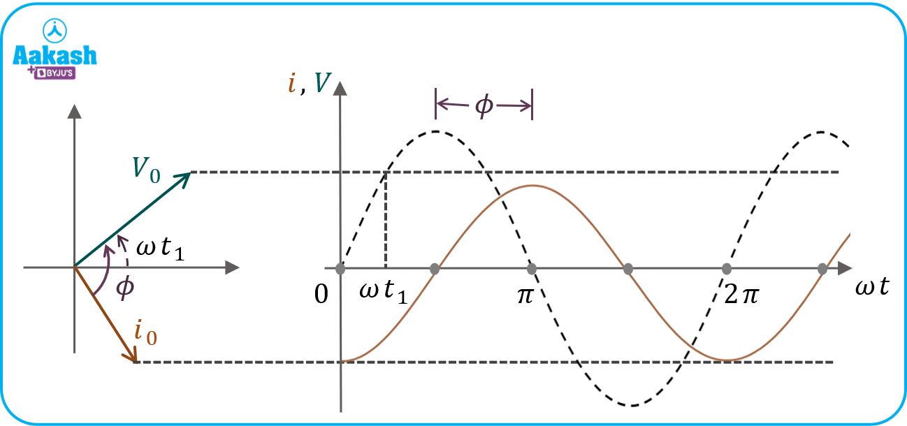
Case1: 
The circuit is predominantly capacitive which suggests that the current is leading the voltage.
 is positive since,
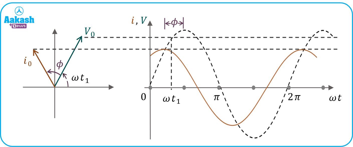
Case2: 
The circuit is predominantly inductive which suggests that the current is lagging the voltage.
is negative since,
Impedance Vs Frequency
 and
and 


Let’s draw Z vs f graph

Value of impedance first decreases then increases. Z is minimum at resonance frequency 
Solved Examples
Q 1. In a series LCR circuit with an AC source, R = 300 Ω, C = 20 μF, L = 1.0 H,  and
and  Hz. Find the reactance of capacitor and inductor?
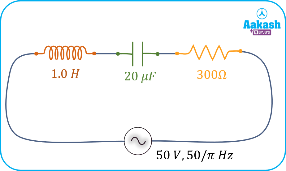
Answer: Given


Reactance of capacitor,


Reactance of inductor,


Q 2. In the previous, find the magnitude of impedance of LCR series circuit?
Answer: Given
We have calculated, and
By using impedance triangle, we can write impedance as


Q 3. In the previous question, calculate the angle of impedance and power factor of the LCR series circuit?
Answer: We know that,


is the angle between current and voltage, so we can calculate power factor as,


Q 4. In the previous LCR series circuit, find the RMS current flowing through the circuit?
Answer: Given,


FAQs
Q 1. How do we decide given elements are in series?
Answer: If the current flowing through the elements is the same then we say that they are in series connection. If voltage across the elements is the same then they are in parallel.
Q 2. Can we directly add the reatances of elements to calculate the net impedance as they are in series connection?
Answer: No, we can not directly add the reactance of inductor and capacitor to resistance because they have 90 degree phase difference with resistance. So we use the formula 
Q 3. What is the application of LCR circuits?
Answer: The LCR series circuit is also known as a tuned circuit or acceptor circuit. In the realm of oscillating circuits, they have a wide range of applications.
Q 4. How the impedance of LCR series circuit depends on the frequency of AC source?
Answer: we know that and are functions of frequency. As frequency increases, increases and decreases. So impedance first decreases then increases.