-
Call Now
1800-102-2727

Full Wave Rectifier, Practice Problems, FAQs

Electric power generated at the generating station is transferred using alternating current. So the voltage that we receive in our home is alternating. How can we use any device which works on DC? Rectifiers are electrical circuits that transform AC into DC. Half-wave and full-wave rectifiers are the two categories into which rectifiers fall. So a full rectifier is mainly used in converting the AC into DC. It has different applications in different electronic circuits. We are using full wave rectifiers on a daily basis in mobile and laptop chargers. The operation and properties of a full wave rectifier will be examined in this article.
Table of Contents
- Full Wave Rectifier
- Parameters of Full Wave Rectifier
- Advantages of Full Wave Rectifier
- Practice Problems
- FAQs
Full Wave Rectifier
A rectifier that transforms the full cycle of alternating electricity into pulsating direct current is referred to as a full wave rectifier. Full wave rectifiers utilise the entire input AC cycle, as opposed to half wave rectifiers, which only do so. The half wave rectifier's lower efficiency can be made up for by the full wave rectifier.
We can construct the full wave rectifier using two different methods. One is a centre tapped full wave rectifier and the other is a bridge rectifier. Construction of these rectifiers is different but their input output waveform relationship is the same.
Centre Tapped Full Wave Rectifier
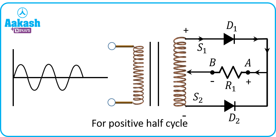
The experimental setup for employing diodes as full wave rectifiers is shown in Figure. The primary transformer receives the alternating signal. Across the load resistance RL, the output signal is visible. We utilise a step down transformer to convert high voltage AC to low voltage AC before rectification since the input AC supply voltage is quite high.
Let S1 be positive and S2 be negative during the positive half of the input signal. Diode D1 is forward biassed in this situation, while D2 is reverse biassed. As a result, only D1 conducts, and current flows from A to B through the load resistance RL.
S1 is now negative and S2 is positive during the negative half of the input signal. D1 is hence forward biassed, whereas D2 is reverse biassed. As a result, only D2 conducts, and current flows from A to B through the load resistance RL.
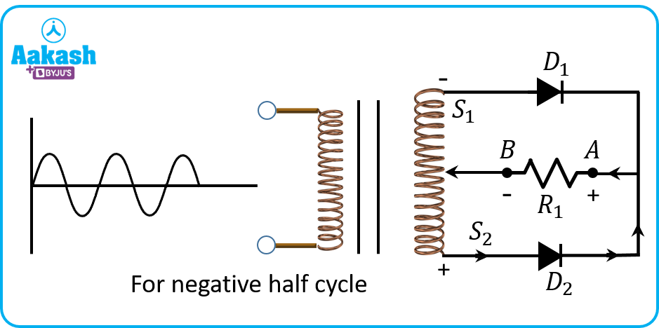
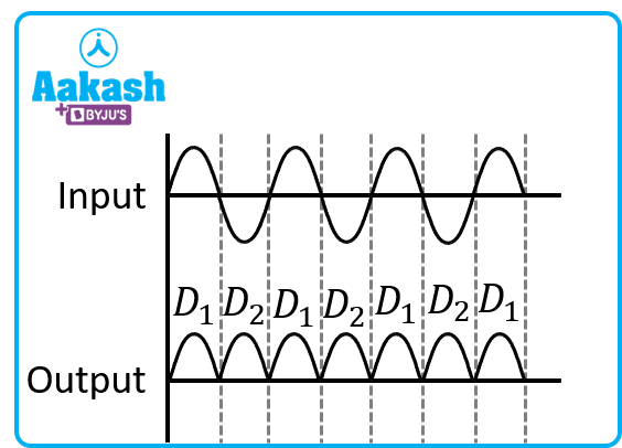
The current always flows through the load resistance in the same direction, regardless of whether the input signal is positive or negative, and full wave rectification is obtained as shown below.
Drawbacks of Centre Tapped Rectifier
- It is difficult to locate the centre of secondary winding of the step down transformer.
- This rectifier is expensive to manufacture because of the bulky transformer.
- Peak inverse voltage of diodes is double as that of half wave rectifier so diodes used here must have high PIV.
Bridge Rectifier
The diagram below illustrates how a bridge rectifier is built. Four diodes D1, D2, D3, and D4 along with a load resistor RL make up the bridge rectifier circuit. To effectively transform alternating current (AC) into direct current (DC), the four diodes are coupled in a closed-loop configuration (DC). The removal of the pricey centre-tapped transformer is this configuration's principal benefit. As a result, both the size and price have decreased.
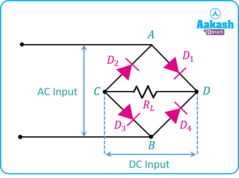
The input signal is applied across terminals A and B, and the load resistor RL, which is linked between terminals C and D, is where the output DC signal is obtained. Only two of the four diodes conduct electricity during each half cycle due to their arrangement. Electric current flows across the pairs D1 and D3 during the positive half cycle. Likewise, during a negative half cycle, electric current flows via diodes D2 and D4. Its output waveform is similar to the centre tapped rectifier.
Advantages of Bridge Rectifier over Centre Tapped
- Need of the centre tapped transformer is eliminated.
- PIV is half of the centre tapped rectifier so the bridge rectifier is suited for high voltage rectification.
- Bridge rectifier is smaller in size as compared to the centre tapped rectifier as there is no bulky transformer required.
- Bridge rectifiers are less expensive than centre tapped transformers because of the removal of the transformer.
Parameters of Full Wave Rectifier
Let's calculate the values of different parameters involved in rectification. Assume input applied voltage is v(t)=Vmsin(t). Here Vm is the peak value of voltage and is angular frequency (rad s-1)
- Peak Inverse Voltage (PIV)
The highest voltage a diode can withstand in the reverse-biassed direction before it breaks down is called peak inverse voltage. The full-wave rectifier's peak inverse voltage is twice that of a half-wave rectifier. PIV=2Vm
- DC Output Voltage
Average value of the output voltage waveform is nothing but DC output voltage. Using mathematical expression for average value we can calculate DC output voltage as considering ideal diodes,
- RMS Output Voltage
We can calculate the RMS value using mathematical expression as,
The second term will be zero, as integration of cosine function over the complete period is zero.
- Form Factor
Form factor is defined as ratio of RMS voltage and Average voltage,
So,
- Peak Factor
Peak factor is the ratio of peak value to RMS value.
- Rectification Efficiency
It is defined as the ratio of DC output power to AC input power. Considering diodes are ideal and no power loss is taking place because of diodes. So
- Ripple Factor
Ripple factor (RF) can be calculated using form factor (FF) by using the formula,
Practice Problems
Q. If the input frequency of the source 50 Hz Then what will be the output waveform frequency of a full wave rectifier?
A. Output waveform has doubled the frequency as that of the input waveform. So output frequency will be 100 Hz.
Q. What is the peak inverse voltage of a full wave rectifier?
A. Peak inverse voltage of a full wave rectifier is two times the maximum source voltage.
Q. State some applications of rectifiers?
A. Modulation, demodulation, and voltage multipliers all employ rectifiers. Rectifiers are used to provide polarised voltage in electric welding.
Q. How many diodes are used in centre tapped full wave rectifiers and bridge rectifiers respectively?
A. In the centre tapped rectifier 2 diodes are used and in case of bridge rectifier 4 diodes are used.
FAQs
Q. What are the disadvantages of full wave rectifiers?
A. When only a low voltage needs to be rectified, full wave rectifiers are ineffective. Because two diodes are linked in series in a fullwave circuit, the voltage loss is doubled due to internal resistances.
Q. How are the frequencies of output waveforms of full wave rectifier and half wave rectifier related?
A. Output waveform frequency of a full wave rectifier is two times the frequency of output waveform of half wave rectifier.
Q. Which rectifier is more efficient?
A. Full wave rectifier has rectification efficiency of 81 % and for half wave rectifier it is 40.5 %. So a full wave rectifier has better rectification capacity as compared to a half wave rectifier.
Q. Where do we use rectifiers?
A. The rectifier's principal function is to convert AC power to DC electricity. Rectifiers are found in practically all electronic equipment's power supplies. The rectifier is generally connected in series with the transformer, a smoothing filter, and potentially a voltage regulator in power supply. For example mobile and laptop chargers.