-
Call Now
1800-102-2727

Exclusive NOR or XNOR Gate

In digital electronics, logic gates play a vital role in the processing and manipulation of binary data. An Exclusive NOR gate generates a high output only when both of its inputs are equal, i.e., either high or low. The Exclusive NOR gate, often abbreviated as XNOR, holds significance in many electronic circuits.
Table of Contents
- What is an Exclusive NOR Gate?
- Symbol and Boolean Expression of Exclusive NOR Gate
- Truth Table of the Exclusive NOR Gate
- Working Principles of the Exclusive NOR Gate
- Equivalent Circuit of Exclusive NOR Gate
- 3 Input Exclusive NOR Gate
- Applications of the Exclusive NOR Gate
- Solved Examples of Exclusive NOR Gate
What is an Exclusive NOR Gate?
The exclusive-NOR Gate, sometimes abbreviated as the XNOR or Ex-NOR Gate, is a digital logic gate that serves as the logical counterpart of the Exclusive-OR or XOR Gate. It is made by joining an Exclusive-OR Gate with a NOT Gate. Interestingly, it has a truth table quite similar to the truth table of the standard NOR gate, but not quite the same.
The XNOR Gate generates a high output, i.e., the logic ‘1’ only when both the inputs are equal, i.e., either high (logic ‘1’) or low (logic ‘0’). That means if the inputs are ‘1’, ‘1’, then the output of the XNOR gate will be ‘1’. Similarly, if the inputs are ‘0’, ‘0’, then the output of the XNOR Gate will also be ‘1’.
The XNOR Gate generates a low output, i.e., the logic ‘0’, only when both the inputs are different, i.e., either of the inputs is high, and the other is low. If the inputs of the gate are ‘1’, ‘0’, then the output of the XNOR Gate will be ‘0’.
Symbol and Boolean Expression of Exclusive NOR Gate
The symbol of the XNOR Gate is shown below. It comprises an Exclusive-OR gate with a small circle at its output, showing inversion or negative operation.

The Boolean expression of the XNOR gate is written as follows:

Truth Table of the Exclusive NOR Gate
|
A |
B |
Y (output) |
|
0 |
0 |
1 |
|
0 |
1 |
0 |
|
1 |
0 |
0 |
|
1 |
1 |
1 |
Working Principles of the Exclusive NOR Gate
Let us see how the XNOR Gate works. For this, we are going to use the standard equation of the XNOR Gate:
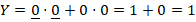
- When A = B = 0
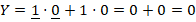
- When A = 1 and B = 0,
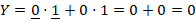
- When A = 0 and B = 1,
- When A = 1 and B = 1
Equivalent Circuit of the Exclusive NOR Gate
We know the XNOR Gate is achieved through the merging of an XOR gate with a NOT gate. The equivalent circuit of the XNOR gate using an XOR gate and a NOT gate is shown below

3 Input Exclusive NOR Gate

Practically, almost all logic gates like AND, OR, NAND, and NOR have a 3-input variant, but unfortunately, a 3-input XNOR gate can not be created and is non-existent. In real life, we only have 2 input XNOR gates. To form a 3-input XNOR gate, we often use two 2-input XNOR gates in cascade, as shown below:

The Truth table of the 3-input XNOR gate is as following:
Truth Table of 3-input XNOR gate
|
A |
B |
C |
Q |
|
0 |
0 |
0 |
1 |
|
0 |
0 |
1 |
0 |
|
0 |
1 |
0 |
0 |
|
0 |
1 |
1 |
1 |
|
1 |
0 |
0 |
0 |
|
1 |
0 |
1 |
1 |
|
1 |
1 |
0 |
1 |
|
1 |
1 |
1 |
0 |
Applications of the Exclusive NOR Gate
Some of the well-known applications of exclusive NOR gate are as follows:
- The XNOR gate can be used to encrypt and decrypt binary data using a secret key.
- The XNOR gate can be used to check the parity of a binary data stream, thus detecting any errors in data transmission.
- The XNOR gate can be used to implement a half-adder circuit which is the basic unit of arithmetic circuits.
Solved Examples of Exclusive NOR Gate
Question 1: Build an Ex-NOR gate using minimum numbers of NAND Gates.
Solution:

Question 2: Create an Ex-NOR gate using only basic gates.
Solution:

Question 3: What will be the boolean expression for the output of a 3-input XNOR gate using A, B and C as inputs?
Solution:
The Boolean expression for a 3-input XNOR gate with A, B and C as inputs will be as follows

Frequently Asked Questions
Question 1: How is an Exclusive NOR gate different from an Exclusive OR gate?
Answer: An Exclusive NOR gate generates a high output when its inputs are equal, whereas an Exclusive OR gate generates high output when its inputs are different.
Question 2: Can an XNOR gate have more than 2 inputs?
Answer: In theory, yes, it can have. But practically, XNOR gates have only 2 inputs.
Question 3: What is the significance of the inversion bubble in the Exclusive NOR gate symbol?
Answer: It signifies that the output produced by the XNOR gate is inverted, i.e., it is the logical complement.