-
Call Now
1800-102-2727

Digital Electronics, Logic Gates, Practice Problems, FAQs

We surround ourselves with numerous applications of digital technology and logic gates. If we consider the example of lift in our building it works totally on the digital circuit. One of the major components of digital electronics is logic gates. One of the known applications of logic gates is the light bulb in the balcony with two switches one inside the room and other outside the room. We can turn it off or on using any of the switches. In this article we will study about the concept of digital electronics and logic gates.
Table of Contents
- Digital and Analog Electronics
- Logic Gates
- Boolean Algebra
- Basic Logic Gates
- Universal Gates
- Additional Gates
- Practice Problems
- FAQs
Digital and Analog Electronics
Let's start by defining analog and digital signals. The signal that can accept any value within the defined range is referred to as an analog signal. The Y-axis of an analog signal amplitude graph with respect to time will be continuous. Below is a graph of the analog signal. Amplifiers and oscillators utilize these signals. Analog Electronics is the name given to electronic circuits that handle analog signals.

Digital signal refers to a signal whose amplitude only accepts discrete values. As a result, the number of amplitude values in a digital signal is finite. Digital electronics refers to electronic circuits that work with digital signals. Below is a graph of a digital signal.

A binary digital signal is what is being shown above. Only two values are allowed for binary signals. It is practical to represent such signals with binary numbers. A binary number only has the digits "0" (for example, 0 V) and "1" (Say, 5 V). In digital circuits, the input and output voltage can only have one of two possible values (represented by 0 or 1).
Working on a digital circuit can be compared to turning on a light switch in our home. Depending on the switch position, the light is either ON or OFF. The output value can be taken to be 1 when the light is ON. The output value is "0" when the light is not on. The location of the light switch is one of the inputs.
Logic Gates
A logic gate is a type of digital circuit that relies on a predetermined logical relationship between its input and output voltages. Semiconductor diodes and transistors are used to construct the logic gates. Each logic gate has a symbol that is unique to it. The truth table is a table that shows how a logic gate functions. All combinations of inputs and matching outputs are included in this table. A Boolean algebraic expression can also be used to represent a logic gate. Writing logical equations that demonstrate how an outcome depends on the mix of inputs is known as boolean algebra. George Boole is the inventor of Boolean algebra..
Boolean Algebra
The category of algebra known as boolean algebra uses variables to represent the true and false truth values, which are often represented by the numbers 1 and 0, respectively. It is applied to simplify and examine digital gates or circuits. It is also known as logical algebra or binary algebra. All contemporary programming languages support it, and it has been crucial to the advancement of digital electronics. Conjunction, disjunction, and negation are three of the crucial operations of boolean algebra. As a result, this algebra differs greatly from elementary algebra, which uses numerical values for variables and performs arithmetic operations like addition and subtraction on them.
Boolean Algebra Operations
The basic operations of Boolean algebra are as follows:
- Conjunction or AND operation ( or )
- Disjunction or OR operation ( or +)
- Negation or Not operation ( or-)
Boolean Expression
A Boolean expression is a logical claim that yields a True or False Boolean value. Sometimes, a statement is expressed using synonyms, such as "Yes" for "True" and "No" for "False." Additionally, digital circuits for True and False employ the values 1 and 0, respectively.
Boolean expressions are those sentences that employ the AND, OR, XOR, and NOT logical operators. Therefore, it is a Boolean expression if we write X AND Y = True.
Terminologies
Boolean algebra is the area of algebra that deals with binary variables and logical operations.
A boolean variable is an alphabet that typically represents logical quantities like 0 or 1. A boolean variable is an alphabet that typically represents logical quantities like 0 or 1.
Boolean function is made up of binary variables, logical operators, constants like 0 and 1, values equal to the operator, and the symbols for parenthesis.
Literal: A literal can be a variable or a variable's complement.
Complement: A bar is placed across a variable to denote the complement, which is the inverse of the variable.
Truth Table
|
A |
B |
AB |
AB |
A |
|
True |
True |
True |
True |
False |
|
True |
False |
False |
True |
False |
|
False |
True |
False |
True |
True |
|
False |
False |
False |
False |
True |
Laws of Boolean Algebra
Commutative Law:
A commutative operation is any binary operation that satisfies the following equation. According to the commutative law, altering the order of the variables has no impact on the output of a logic circuit.
A+B=B+A
AB=BA
Associative Law
It claims that since their effects are the same, the sequence in which the logic operations are carried out is unimportant.
(AB)C=A(BC)
(A+B)+C=A+(B+C)
Distributive Law
The following requirements are set down under distributive law:
A. ( B + C) = (A. B) + (A. C)
A + (B. C) = (A + B) . ( A + C)
AND Law
A0=0
A1=A
AA=A
AA=0
OR Law
A+0=A
A+1=1
A+A=A
A+A=1
Inversion Law
A=A
Theorems
De Morgan’s First Law: The first law states that the complement of the product of the variables is equal to the sum of their individual complements of a variable.
A.B= A+B
The following truth table illustrates how De Morgan's First Law can be verified:
|
A |
B |
A |
B |
A.B |
A+B |
|
0 |
0 |
1 |
1 |
1 |
1 |
|
0 |
1 |
1 |
0 |
1 |
1 |
|
1 |
0 |
0 |
1 |
1 |
1 |
|
1 |
1 |
0 |
0 |
0 |
0 |
De Morgan’s Second Law: The second law states that the complement of the sum of variables is equal to the product of their individual complements of a variable.
(A+B)=A.B
The following truth table illustrates how De Morgan's Second Law can be verified:
|
A |
B |
A |
B |
(A+B)’ |
A.B |
|
0 |
0 |
1 |
1 |
1 |
1 |
|
0 |
1 |
1 |
0 |
0 |
0 |
|
1 |
0 |
0 |
1 |
0 |
0 |
|
1 |
1 |
0 |
0 |
0 |
0 |
Basic Logic Gates
There are three basic logic gates:
- NOT Gate
- OR Gate
- AND Gate
Let’s see the truth table, symbolic representation and boolean expression of each gate one by one.
NOT Gate
With only one input and one output, this gate is the simplest. It creates an output that is an inverted counterpart of the input, producing a "1" output if the input is a "0," and vice versa. It is also referred to as an inverter because of this. The truth table for this gate and its often used symbol are depicted in the figure below.
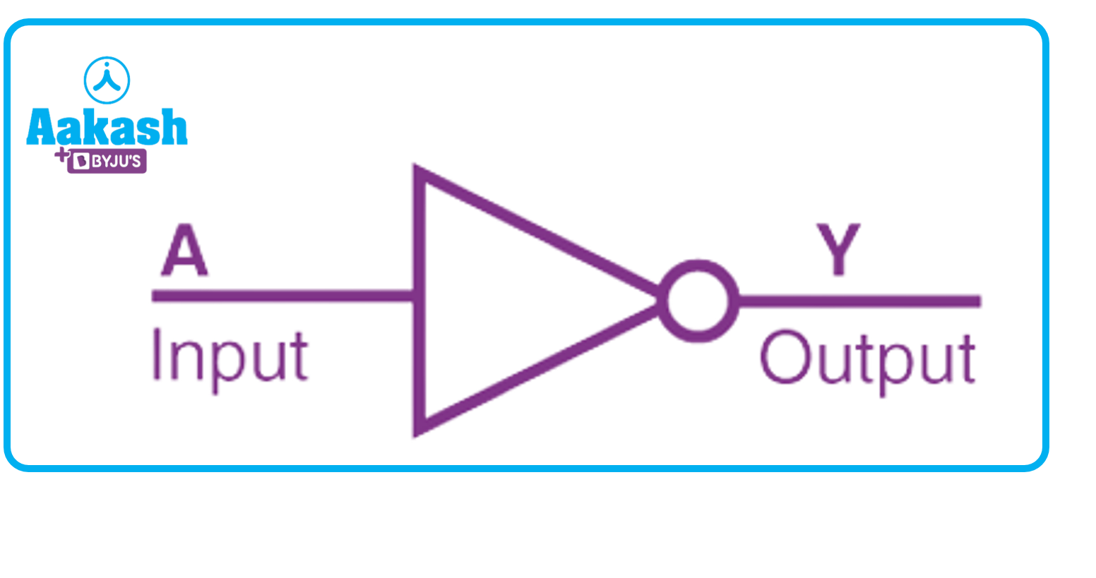
Boolean Expression: Y=A
Truth Table
|
A |
Y |
|
0 |
1 |
|
1 |
0 |
An analogous electrical circuit which behaves the same as NOT gate as shown below. When the switch is ON then the bulb is OFF and when the switch is OFF the bulb is ON.

NOT gate cannot be realized by using the diodes but we can use the transistor to realize the NOT gate.

Here A is the input and Y is the output.
OR Gate
The addition sign (+) is known as OR in Boolean algebra. The OR gate is a component that joins A and B to get the outcome Y. A device with two or more inputs and one output is called an OR gate. A two-input OR gate with A and B inputs and Y output is represented by the logic symbol in the illustration.
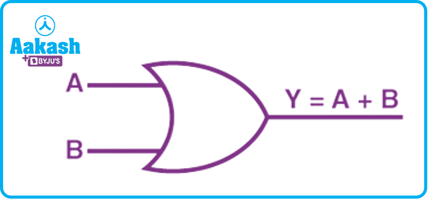
The output Y is 1 when either input A or input B or both are 1s, i.e., if any of the input is high, the output is high.
Boolean Expression: Y=A+B
Truth Table
|
A |
B |
Y |
|
0 |
0 |
0 |
|
0 |
1 |
1 |
|
1 |
0 |
1 |
|
1 |
1 |
1 |
An analogous electric circuit is shown below. There are two switches A and B in parallel. If any of the switches is ON then the bulb will be ON and if both the switches are OFF then the bulb will be OFF.

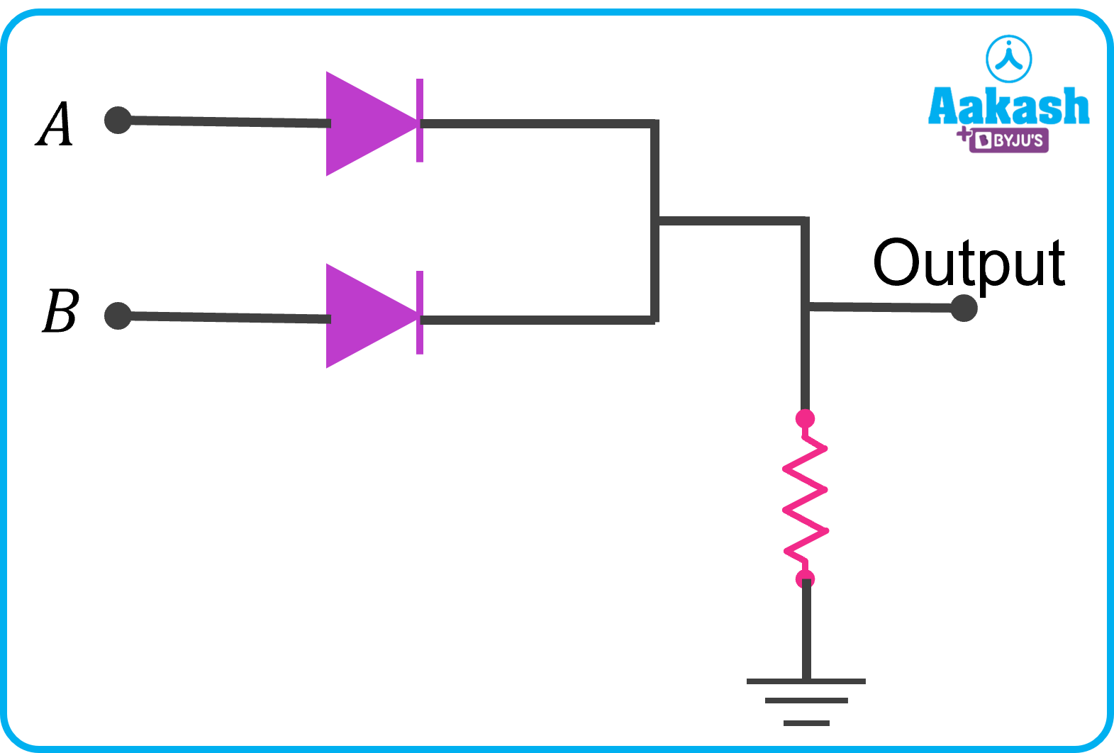
Realization of OR gate using Diodes
AND Gate
In Boolean algebra, the multiplication symbol dot () is referred to as AND. The AND gate is a component that combines the inputs A and B to produce the output Y. A device with two or more inputs and one output is called an AND gate. The graphic displays the two-input AND gate's logic symbol, which has Y as the output and inputs A and B.
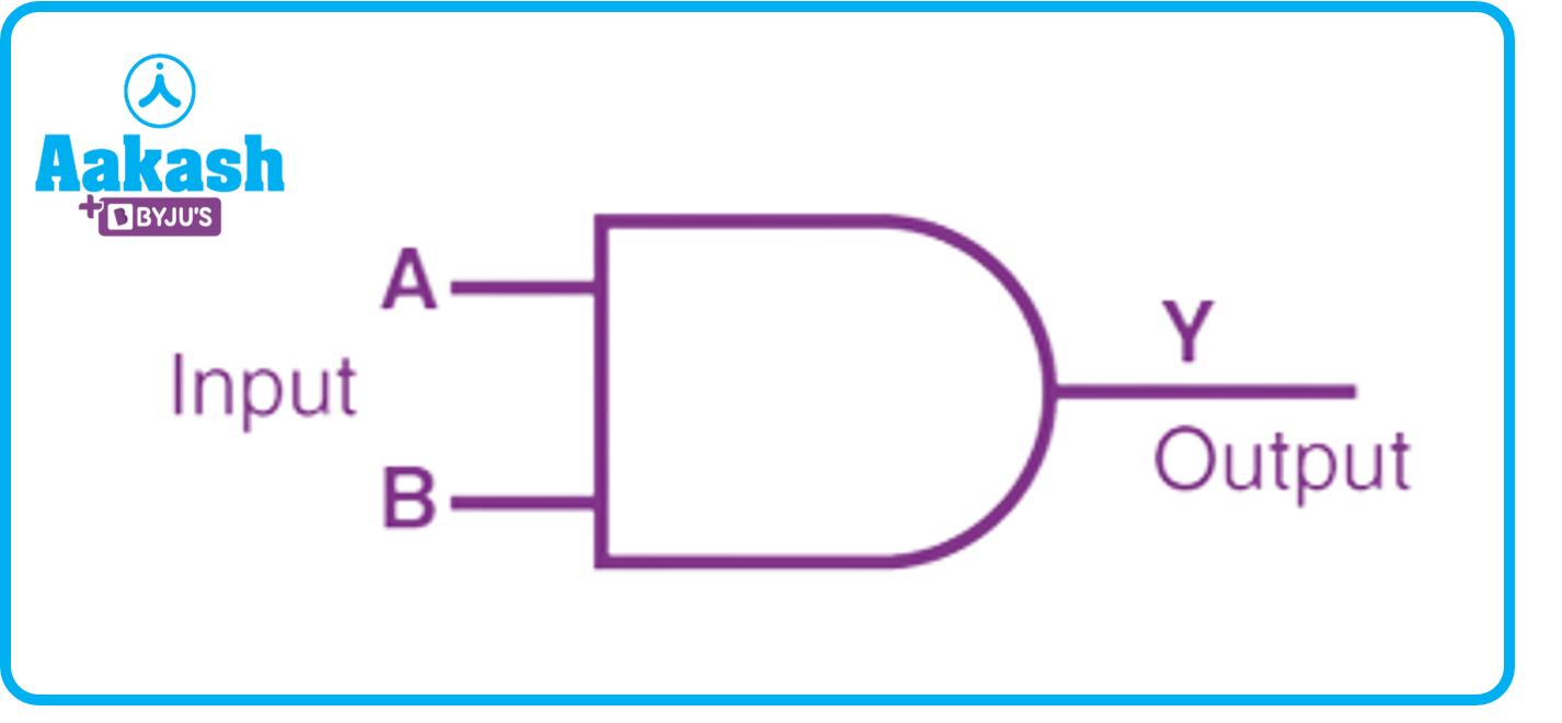
The logic of this gate is that when A and B are high, then only output Y is high, otherwise Y is low.
Boolean Expression: Y=AB
Truth Table
|
A |
B |
Y |
|
0 |
0 |
0 |
|
0 |
1 |
0 |
|
1 |
0 |
0 |
|
1 |
1 |
1 |
An analogous electric circuit is shown below. Two switches A and B are in series connection. So the bulb will be ON only when both the switches are ON.

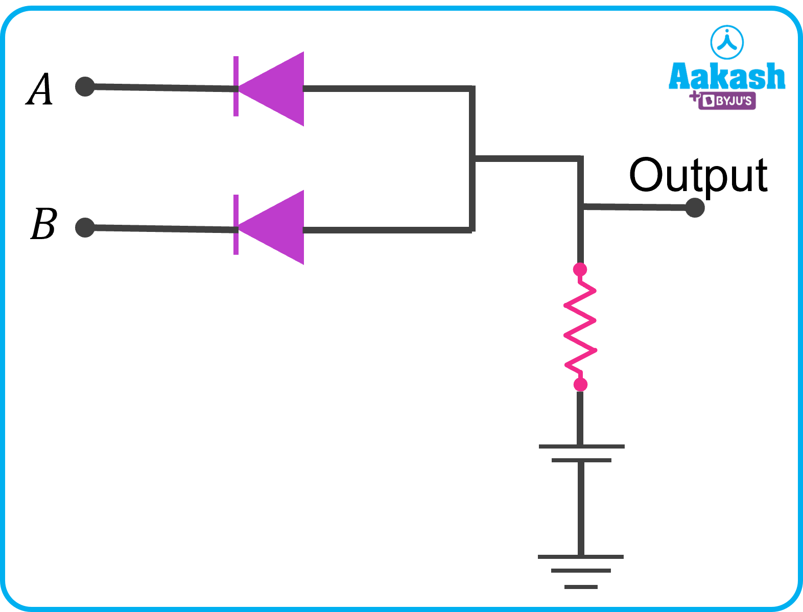
Realization of AND gate using Diodes
Universal Gates
We can design any digital system using repetition and different combinations of gates called Universal Gate. There are two universal gates as follows:
- NAND
This universal gate is the combination of AND and NOT gate.
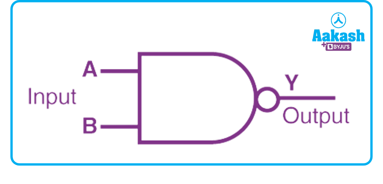
Y=AB
Truth Table
|
A |
B |
Y |
|
0 |
0 |
1 |
|
0 |
1 |
1 |
|
1 |
0 |
1 |
|
1 |
1 |
0 |
- NOR
This universal gate is the combination of OR gate and NOT gate.
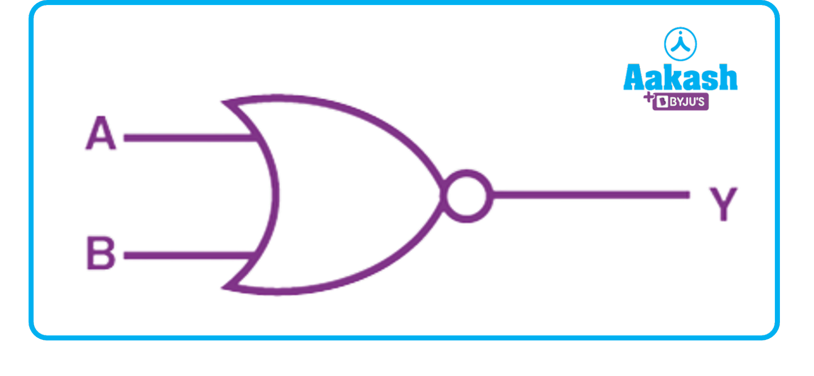
Y=A+B
Truth Table
|
A |
B |
Y |
|
0 |
0 |
1 |
|
0 |
1 |
0 |
|
1 |
0 |
0 |
|
1 |
1 |
0 |
Additional Gates
There are two more gates that are being used to design digital systems.
- XOR
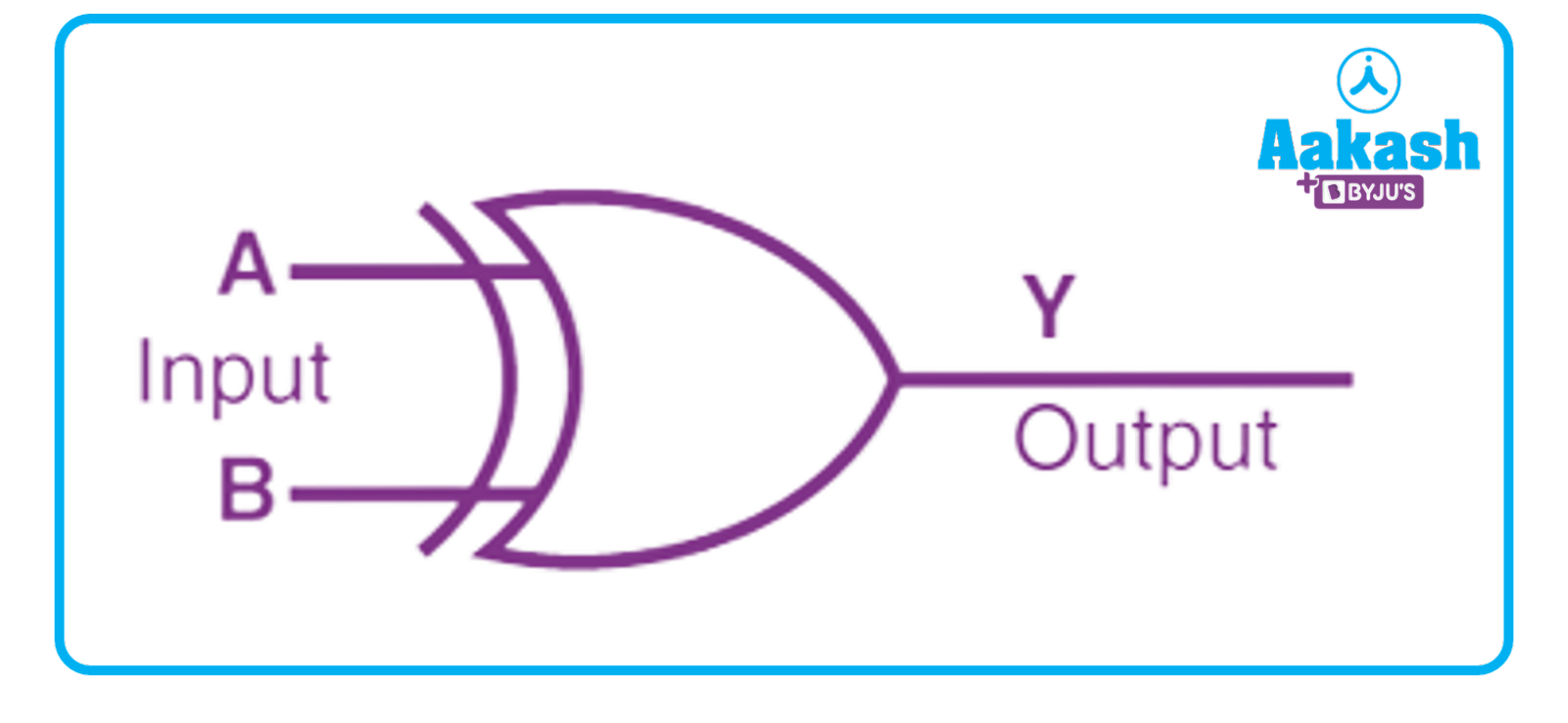
(recreate this image)
Y=AB=AB+AB
Truth Table
|
A |
B |
Y |
|
0 |
0 |
0 |
|
0 |
1 |
1 |
|
1 |
0 |
1 |
|
1 |
1 |
0 |
- XNOR
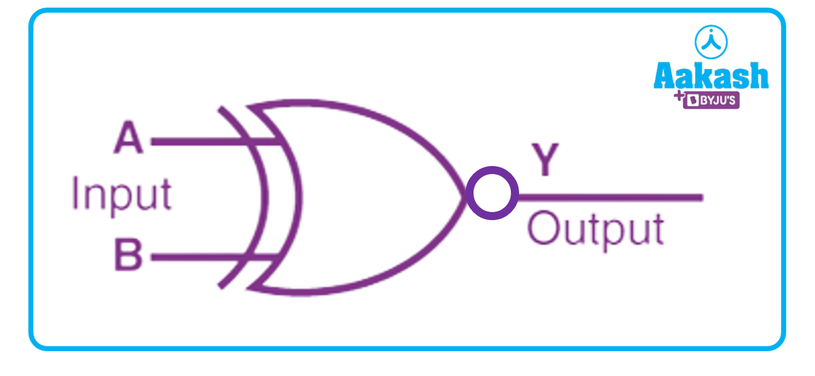
Y=AB=AB+AB
Truth Table
|
A |
B |
Y |
|
0 |
0 |
1 |
|
0 |
1 |
0 |
|
1 |
0 |
0 |
|
1 |
1 |
1 |
Practice Problems
Q. From the following logic circuit find the boolean expression for the output?

A. From the logic circuit,
One gate is OR gate whose inputs are A and B so its output will be (A+B).
The second gate is the AND gate whose one input is C and other input is the output of OR gate.
So Y=(A+B)C
Q. Find the output waveform of the OR gate for the following input waveforms A and B shown?

A. Output of OR gate is high when either or both the inputs are high. So if we consider the above two waveforms A and B then we will get the following output waveform. You can use the following truth table for your reference.
Truth Table
|
A |
B |
Y |
|
0 |
0 |
0 |
|
0 |
1 |
1 |
|
1 |
0 |
1 |
|
1 |
1 |
1 |

Q. Simplify the following boolean expression
Y=AB+A(B+C)+B(B+C)
A. Y=AB+A(B+C)+B(B+C)
Y=AB+AB+AC+BB+BC
Y=AB+AC+B+BC
Y=AB+AC+B(1+C)
Y=AB+AC+B1
Y=AB+AC+B
Y=B(1+A)+AC
Y=B1+AC
Y=B+AC
Y=AC+B
Q. Find the output waveform of the AND gate for the following input waveforms A and B shown?

A. Output of AND gate is high only when both the inputs are high. So if we consider the above two waveforms A and B then we will get the following output waveform. You can use the following truth table for your reference.
Truth Table
|
A |
B |
Y |
|
0 |
0 |
0 |
|
0 |
1 |
0 |
|
1 |
0 |
0 |
|
1 |
1 |
1 |

Q. Find the truth table for three input AND gate?
A. In the case of AND gate output is high only when all the inputs are high. So by using this logic we can get the truth table as shown below. Here A, B, C are three inputs and Y is the output.
|
A |
B |
C |
Y |
|
0 |
0 |
0 |
0 |
|
0 |
0 |
1 |
0 |
|
0 |
1 |
0 |
0 |
|
0 |
1 |
1 |
0 |
|
1 |
0 |
0 |
0 |
|
1 |
0 |
1 |
0 |
|
1 |
1 |
0 |
0 |
|
1 |
1 |
1 |
1 |
FAQs
Q. Output of the OR gate is 1
- If both inputs are zero
- If either or both inputs are 1
- Only if both inputs are 1
- If either input is zero
A. Output of the OR gate is 1 when either or both the inputs are 1. So option (b) is correct.
Q. If the one input of AND gate is kept at logic 1 then what will be the output?
A. If one of the inputs is at logic 1 then the output of the AND gate will be the same as the other input.
Q. If the one input of OR gate is kept at logic 1 then what will be the output?
A. If any of the inputs of OR gate is high then the output is high. So in this case output of OR gate will be 1.
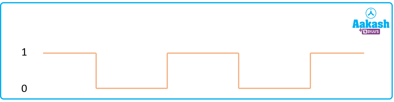
Q. Find the output waveform of the NOT gate having input signal as shown below?
A. NOT gate invert the input. So when input is high output will be low and when input is low output will be high. So the output waveform will look like this: