-
Call Now
1800-102-2727


Half-Wave and Full-Wave Rectifiers: Working, Circuit, Formula & Applications

Rectification is the process by which AC is converted into DC. Almost all electronic devices require DC for proper operation, but electrical power is generally supplied as AC.
Some common applications of rectifiers include:
- Power supplies
- Battery chargers
- Radio and television circuits
- Digital measuring instruments
The diodes used in a rectifier circuit allow current in one direction only.
Types of Rectifiers
Rectifiers are broadly classified into:
- Half-Wave Rectifier
- Full Wave Rectifier
Each of them differs in: circuit design, efficiency, ripple factor, and quality of output voltage.
Half-Wave Rectifier
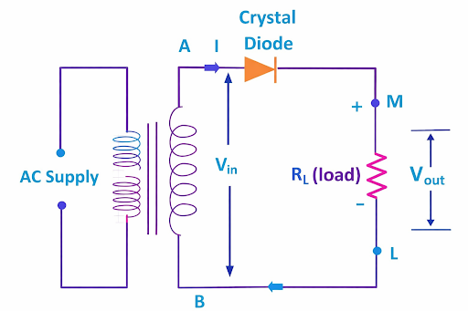
Circuit diagram of a half-wave rectifier: an AC source connected to the primary of a step-down transformer, whose secondary connects in series with a single diode and a load resistor. Half-wave rectifier circuit AC transformer diode RL
A half-wave rectifier is a circuit that allows only half of the AC input cycle to pass through and blocks the other half. It uses only one diode to convert AC into pulsating DC.
Half-Wave Rectifier Construction
The basic components are: AC supply, step-down transformer, one PN-junction diode, load resistor (RL).
Circuit Description: The transformer steps down the AC voltage to the desired level. The secondary of the transformer is connected in series with the diode and load resistor. Output is taken across the load resistor.
Working Principle of Half-Wave Rectifier
This process relies on the behaviour of the diode as it encounters each half of the AC wave.
Positive Half Cycle: The diode is forward-biased. There is a flow of current in the circuit. Voltage exists across the load. The output serves as a copy of the waveform.
Negative Half Cycle: The diode is reverse-biased. No current passes through the circuit. The output voltage is zero.
Hence, only one half of the AC waveform is utilised.
Input and Output Waveforms
Input Waveform: A sinusoidal AC waveform. It has both positive and negative half-cycles.
Output Waveform: Only positive half cycles. Negative half-cycles are eliminated. The output is a pulsating DC.
Mathematical Analysis of Half-Wave Rectifier
Let us go through the mathematical analysis of a half-wave rectifier.
Peak Input Voltage: Let the peak secondary voltage = Vm
DC Output Voltage:
DC Output Current:
Where Vm = peak voltage, Im = current peak value.
Efficiency of Half-Wave Rectifier
The efficiency of the rectifier is expressed as the ratio of DC output power to the AC input power.
Maximum Efficiency: 40.6%
This low efficiency is attributable to: only one half-cycle of the input signal being utilised, and power loss.
Ripple Factor of Half-Wave Rectifier
Ripple factor expresses the amount of AC contained within the DC output.
Ripple Factor Value: 1.21
A high ripple factor reveals poor quality DC output.
Peak Inverse Voltage (PIV)
Peak Inverse Voltage is the highest reverse-voltage rating a diode can withstand without breaking down.
PIV for Half-Wave Rectifier: PIV = Vm
This voltage must be handled properly using a diode.
Advantages of Half-Wave Rectifier
- Simple circuit design
- Low cost
- Requires only one diode
- Easy to construct and understand
Disadvantages of Half-Wave Rectifier
- Low efficiency
- High ripple content
- Poor voltage regulation
- Insufficient for high-power applications
- Output is not a smooth DC
Applications of Half-Wave Rectifier
- Low-power electronic circuits
- Signal demodulation
- Battery charging – small batteries
- Educational and laboratory experiments
Full Wave Rectifier
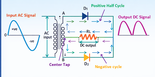
A Full-Wave Rectifier converts both cycles of the AC input signal into a DC output. Its efficiency is higher, and it gives a smoother DC than the half-wave rectifier.
Types of Full Wave Rectifier
The two main types: centre-tapped full-wave rectifier and bridge rectifier. Both types provide full-wave rectification in their respective circuit arrangements.
Centre-Tapped Full Wave Rectifier
Some components are: centre-tapped transformer, two diodes, load resistor. The centre tap is a reference point for the output.
Working of Centre-Tapped Full Wave Rectifier
Positive Half Cycle: The upper diode is conducting. The lower diode is reverse-biased. Current flows in one direction through the load.
Negative Half Cycle: During the negative half cycle, the other diode conducts. The upper diode is reverse-biased. Current passing through the circuit is always in the same direction.
Therefore, both phases of the AC signal are used.
Bridge Rectifier
The construction is as follows: four diodes in a bridge circuit. A centre-tapped transformer is not required. The load is connected across the bridge output.
Working of Bridge Rectifier
Positive Half Cycle: Two diagonally opposite diodes conduct. Current passes in one direction towards the load.
Negative Half Cycle: The other two diodes conduct. The direction of the current through the load is not affected.
This provides a continuous DC output.
Input and Output Waveforms of Full Wave Rectifier
Input Waveform: Standard sinusoidal AC waveform.
Output Waveform: Both half cycles produce positive output. The frequency of the output is twice the frequency of the input. The output is a pulsating DC with a lower ripple.
Mathematical Analysis of Full Wave Rectifier
DC Output Voltage:
DC Output Current:
The values of these components for this design would be twice those for a half-wave rectifier.
Efficiency of Full Wave Rectifier
Maximum efficiency: 81.2%
This value is considerably higher compared to the half-wave rectifier. This is due to the reduced power loss and full utilisation of the input signal.
Ripple Factor of Full Wave Rectifier
Ripple Factor Value: 0.48
This is an indication of better quality DC output, and less filtering is required compared to a half-wave rectifier.
Peak Inverse Voltage in Full Wave Rectifier
Centre-Tapped Rectifier: PIV = 2Vm
Bridge Rectifier: PIV = Vm
Bridge rectifiers have a lower PIV demand per diode.
Centre-Tapped and Bridge Rectifier Comparison
Centre-Tapped Rectifier: requires a special transformer, uses two diodes, requires diodes with a higher PIV rating.
Bridge Rectifier: no centre tap required, uses four diodes, smaller PIV rating per diode, more commonly used.
Advantages of a Full Wave Rectifier
- High efficiency
- Lower ripple content
- Improved regulation of voltage
- Higher DC output voltage
- Suitable for power supply circuits
Drawbacks of the Full Wave Rectifier
- More complex circuit than a half-wave rectifier
- Higher cost
- Uses more components
Applications of the Full Wave Rectifier
- Power supply units
- DC motor drives
- Battery chargers
- Audio amplifiers
- Industrial electronic systems
Conclusion
While most electronic systems require DC, most of the electrical energy distributed in our homes is AC. Rectifiers play a critical role in power conversion. The half-wave rectifier, though simple and inexpensive, has a number of disadvantages, such as low efficiency and high ripple content. They are suited for low-power applications only.
Purity, efficiency, and performance are better in a full-wave rectifier, either centre-tapped or bridge type. Because of these reasons, modern power supply circuits widely employ full-wave rectifiers.
The working principles, advantages, and limitations of both rectifiers will now be explained through the study and design of electronic power systems.
FAQs
Q1. Why is a full-wave rectifier more efficient than a half-wave rectifier?
A full-wave rectifier uses both halves of the AC input signal, reducing power loss and ripple content. This leads to higher DC output and better efficiency compared to a half-wave rectifier.
Q2. What is Peak Inverse Voltage (PIV)?
Peak Inverse Voltage is the maximum reverse voltage that a diode can withstand without breakdown. It is Vm for half-wave and bridge rectifiers, and 2Vm for centre-tapped rectifiers.
Q3. Why is filtering required after rectification?
Rectifier output is pulsating DC containing AC ripples. Filters smoothen this output by reducing ripple content to produce a nearly steady DC voltage.
Q4. Which rectifier is most commonly used in power supplies and why?
Bridge rectifiers are commonly used because they do not require a centre-tapped transformer, have lower PIV requirements per diode, and provide efficient full-wave rectification.

NEET Related Links
JEE MAIN Related Links
JEE Advanced Related Links
JEE Advanced Eligibility Criteria
JEE Advanced Chemistry Syllabus
JEE Advanced Registration Dates
CUET Related Links
Important Topics
Anemometer : Measurement of Wind Speed
Angular Acceleration Atomic Theory Audible and Inaudible Sound Average Speed and Average Velocity Average Velocity Avogadros Number Avogadros Hypothesis Azimuthal Quantum Number Balanced Force Bar Magnet Biconvex Lens Boyles Law Buoyancy Calorimeter Carnot Engine Celestial Bodies Centripetal And Centrifugal Force Concave and Convex Lenses Concave Convex Mirrors Contact and Non Contact Force Controlled Thermonuclear Fusion Convection Currents Convex Lens Convex Mirror Destructive Interference Difference Between Conduction Convection and Radiation Difference Between Electric Field and Magnetic Field Difference Between Heat And Temperature Difference Between Series And Parallel Circuits Differences Between Acceleration And Velocity Distance and Displacement Distance Time Graph Electrical Force : Electric Forces and Their Types Electromagnetic Waves : Definition, Equation and Properties of Electromagnetic Waves Electromagnetism Electron Spin Fluid Flow : Bernoullis Equation Derivation and Fluid Mechanics Fluid Friction : Types and Factors of Fluid Friction Frames of Reference : Inertial and Non- Inertial Frame of Reference Frequency and Wavelength Frictional Force Importance of Hydrosphere Instantaneous Speed and Velocity Introduction to Motion Kinetic and Potential Energy Difference Law Of Conservation of Energy Layers of the Earth Light Energy Light Sources List of physics scientists and Their inventionsLoudness of Sound
Magnetic Dipole Moment Magnetic Field Non - Contact Force Non - Renewable Energy Ohms Law Optics P Wave Physics Symbols Plane Mirrors Poissons Ratio Projectile Motion Properties of Water : Anomalous Expansion of Water Radius of Gyration Reflection of Light Reflection of Waves Relative Density Resonance Reverberation Rolling Friction Rotation and Revolution Screw Gauge Semiconductors and Insulators Sliding Friction Speed Time Graphs Static Friction Stefan Boltzmann Law Stress Tension Tension Force Thermometer: Clinical Laboratory Thermometer Types of Rocks Types of Waves Uniform Motion and Non Uniform Motion Unit of Voltage Uses of Convex Lens Uses Of Convex Mirror Uses of Electromagnet Uses of Optical Fibre Wave Wavelength of Light What is Scattering of Light Working of Electric Bell Conventional and Non-conventional Sources of Energy Buoyant Force Bulk Modulus of Elasticity Bernoulli’s Principle Angular Momentum Difference Between Speed And Velocity ForceUnit of Heat
Difference between Distance and Displacement Simple Microscope Derivation Of Equation Of Motion Thermometer: Clinical & Laboratory Thermometer Difference between Concave and Convex LensDerivation Of Lens Maker Formula
Unit Of Pressure Velocity Uses of Plane Mirror
Wave Theory of Light
Unit of Density Unit of Light Unit of Force Unit of Magnetic Field Unit of wavelength Unit of Viscosity Uses of Electroplating Young's Modulus
What is the Scattering of Light
Lenz Law Space Wave Propagation Schrodinger Wave Equation Relation between Fahrenheit and Celsius Refractive Index Potentiometer Working Pascal Law Oscillatory Motion Optical Instruments Newton's Laws of Motion - First Law Modulation and Demodulation Magnetic Flux Lens Formula and Magnification Kaleidoscope Faradays Law Epsilon Naught Value Energy Bands Electrostatics Electroscope AC Generator Unit of Current Lithosphere Bending Equation Derivation Difference Between Pound and Kilogram Semiconductor Devices OTEC - Ocean Thermal Energy Conversion Hall Effect Rectilinear Propagation of Light Difference Between Ammeter and Voltmeter Coefficient of Linear Expansion Ampere’s Law Cyclone and Thunderstorm Save The Environment From Pollution Particle Nature of Light Types of DC Motor Uses Of Transistor Derivation of Phase Rule Unit of Humidity

 Call Now
 Let's Chat
 Share
Share