
Inductive Reactance And Capacitive Reactance

When alternating current (AC) circuits are studied, two key concepts that emerge are inductive reactance and capacitive reactance. These are the measures of how inductors and capacitors oppose the flow of alternating current. Inductors and capacitors behave differently under the application of AC. Inductive reactance is usually related to the magnetic field produced by the current-carrying coil or wire, whereas capacitive reactance is correlated to the changing electric field between two conducting plates or surfaces that are separated by some insulating medium.
Inductive reactance is the resistance provided by the inductor in an AC circuit to the flow of AC current. It is denoted by (XL) and expressed in units of ohms (Ω). Inductive reactance is low in the case of lower frequencies and high in the case of higher frequencies. For DC current, it is negligible. An inductor is a loop of wire that accumulates energy in the form of a magnetic field when current passes through it. In AC circuits, the current is always reversing direction, so the magnetic field surrounding the inductor is also always reversing. According to Faraday's Law of Electromagnetic Induction, the reversing magnetic field creates an opposing voltage, or back emf (electromotive force), in the coil. This opposing voltage opposes changing current.
The formula for inductive reactance is:

Through this formula, we know that inductive reactance increases with frequency. That means at higher frequencies, an inductor offers greater resistance to the AC current.
(where f = 0), the inductive reactance is zero, and the inductor behaves like a simple wire. In an AC circuit, the current in an inductor lags behind the voltage by 90 degrees. This lag is due to the back emf opposing the change in current.

From the formula above, we can understand that capacitive reactance is lower with higher frequencies. This means that capacitors offer less opposition to high-frequency signals. At very low frequencies (in DC, where f = 0), the capacitive reactance is very high and practically blocks DC current. In an AC circuit, the capacitor current leads the voltage by 90 degrees. This is due to the fact that the capacitor begins to pass current as soon as the voltage starts to change, even before the voltage reaches its peak.
Graph Representation
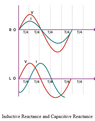
The graph indicates the phase relationship between current (I) and voltage (V) in capacitive and inductive AC circuits. In the inductive circuit (upper graph), voltage precedes current by 90° because the inductor resists a change in current. In the capacitive circuit (lower graph), current precedes voltage by 90° because the capacitor enables current to respond rapidly to changes in voltage. Therefore, voltage leads current in inductive circuits and current leads voltage in capacitive circuits.
Difference between Inductive Reactance and Capacitive Reactance
| Characteristics | Inductive Reactance (XL) | Capacitive Reactance (XC) |
|---|---|---|
| Device | Inductor | Capacitor |
| Formula |  |
 |
| Depends on | Frequency (f) and inductance (L) | Frequency (f) and capacitance (C) |
| Effect of Frequency | Increases with an increase in frequency | Decreases with an increase in frequency |
| Behaviour in DC (f = 0) |  |
 |
| Phase | Current lags voltage by 90° | Current leads voltage by 90° |
| Energy Stored | In the form of a magnetic field | In the form of an electric field |
Summing Up
Inductive and capacitive reactance are fundamental in learning why AC circuits will behave differently from DC circuits. Inductive reactance goes up with frequency and makes current lag behind voltage, whereas capacitive reactance goes down with frequency and makes current lead voltage. Both are crucial in regulating current flow.
Frequently Asked Questions
Q1. What are the applications of inductive and capacitive reactance?
They are used in filters, tuning circuits, power factor correction, and signal processing in AC electrical and electronic systems.
NEET Related Links
JEE MAIN Related Links
JEE Main marks vs rank vs percentile
JEE Advanced Related Links
JEE Advanced Eligibility Criteria
JEE Advanced Chemistry Syllabus
JEE Advanced Registration Dates
CUET Related Links
Important Topics
Anemometer : Measurement of Wind Speed
Angular Acceleration Atomic Theory Audible and Inaudible Sound Average Speed and Average Velocity Average Velocity Avogadros Number Avogadros Hypothesis Azimuthal Quantum Number Balanced Force Bar Magnet Biconvex Lens Boyles Law Buoyancy Calorimeter Carnot Engine Celestial Bodies Centripetal And Centrifugal Force Concave and Convex Lenses Concave Convex Mirrors Contact and Non Contact Force Controlled Thermonuclear Fusion Convection Currents Convex Lens Convex Mirror Destructive Interference Difference Between Conduction Convection and Radiation Difference Between Electric Field and Magnetic Field Difference Between Heat And Temperature Difference Between Series And Parallel Circuits Differences Between Acceleration And Velocity Distance and Displacement Distance Time Graph Electrical Force : Electric Forces and Their Types Electromagnetic Waves : Definition, Equation and Properties of Electromagnetic Waves Electromagnetism Electron Spin Fluid Flow : Bernoullis Equation Derivation and Fluid Mechanics Fluid Friction : Types and Factors of Fluid Friction Frames of Reference : Inertial and Non- Inertial Frame of Reference Frequency and Wavelength Frictional Force Importance of Hydrosphere Instantaneous Speed and Velocity Introduction to Motion Kinetic and Potential Energy Difference Law Of Conservation of Energy Layers of the Earth Light Energy Light Sources List of physics scientists and Their inventionsLoudness of Sound
Magnetic Dipole Moment Magnetic Field Non - Contact Force Non - Renewable Energy Ohms Law Optics P Wave Physics Symbols Plane Mirrors Poissons Ratio Projectile Motion Properties of Water : Anomalous Expansion of Water Radius of Gyration Reflection of Light Reflection of Waves Relative Density Resonance Reverberation Rolling Friction Rotation and Revolution Screw Gauge Semiconductors and Insulators Sliding Friction Speed Time Graphs Static Friction Stefan Boltzmann Law Stress Tension Tension Force Thermometer: Clinical Laboratory Thermometer Types of Rocks Types of Waves Uniform Motion and Non Uniform Motion Unit of Voltage Uses of Convex Lens Uses Of Convex Mirror Uses of Electromagnet Uses of Optical Fibre Wave Wavelength of Light What is Scattering of Light Working of Electric Bell Conventional and Non-conventional Sources of Energy Buoyant Force Bulk Modulus of Elasticity Bernoulli’s Principle Angular Momentum Difference Between Speed And Velocity ForceUnit of Heat
Difference between Distance and Displacement Simple Microscope Derivation Of Equation Of Motion Thermometer: Clinical & Laboratory Thermometer Difference between Concave and Convex LensDerivation Of Lens Maker Formula
Unit Of Pressure Velocity Uses of Plane Mirror
Wave Theory of Light
Unit of Density Unit of Light Unit of Force Unit of Magnetic Field Unit of wavelength Unit of Viscosity Uses of Electroplating Young's Modulus
What is the Scattering of Light
Lenz Law Space Wave Propagation Schrodinger Wave Equation Relation between Fahrenheit and Celsius Refractive Index Potentiometer Working Pascal Law Oscillatory Motion Optical Instruments Newton's Laws of Motion - First Law Modulation and Demodulation Magnetic Flux Lens Formula and Magnification Kaleidoscope Faradays Law Epsilon Naught Value Energy Bands Electrostatics Electroscope AC Generator Unit of Current Lithosphere Bending Equation Derivation Difference Between Pound and Kilogram Semiconductor Devices OTEC - Ocean Thermal Energy Conversion Hall Effect Rectilinear Propagation of Light Difference Between Ammeter and Voltmeter Coefficient of Linear Expansion Ampere’s Law Cyclone and Thunderstorm Save The Environment From Pollution Particle Nature of Light Types of DC Motor Uses Of Transistor Derivation of Phase Rule Unit of Humidity
Difference between Land Breeze and Sea Breeze
Relation Between Critical Angle And Refractive Index
Derivation of Escape Velocity Unit of Speed Elastic Collision Linear Velocity Reversible and Irreversible Processes Relation Between Density And VolumeRelation Between Group Velocity And Phase Velocity
Thermal Stress
Mirrors Conversion of Units Modulation Unit of Weight Stokes Law Derivation Kirchhoff’s Second Law Zener Diode as a Voltage Regulator Quark Difference Between Discovery and Invention Nuclear Fission UltrasoundPrinciple Of Calorimetry
Differences Between Magma and LavaTypes Of Wind
Difference Between Work and Energy Schottky Diode Kinetic Theory Of Gases Thermal Properties of Materials Relation Between Kinetic Energy And Momentum Work Done By A Variable Force Solenoid and Toroid Difference between Light Microscope and Electron Microscope Doppler Effect Derivation Determine Refractive Index of a Glass Slab using a Travelling Microscope Relation between Torque and Speed Current Density Electric Displacement Impending Motion Latent Heat of WaterInfrared Radiation
Vector Product Of Two VectorsAlpha Decay1
Centripetal Acceleration
Newton's Third Law Of MotionBiogas Energy
Tracing the Path of a Ray of Light Passing Through a Rectangular Glass Slab
Unit of Conductivity
PulleyResistor
LCR Circuit
Difference Between Force and Pressure Viscosity Einstein's Explanationx Sea Breeze and Land Breeze Types of Lever Permeability Adiabatic Process Fleming's Left Hand Rule And Right Hand Rule Spherical Mirrors Heat Transfer By Convection Stress and Strain Displacement Current Unit of Electric Field Electromagnetic Induction Diode Critical Velocity Carbon Resistor Electric Charge Derivation of Continuity Equation Mach NumberCoherent Sources
Rigid Bodies
Resolving Power of a Microscope and TelescopeAngular Displacement
Unit of Momentum
Chandrasekhar Limit
Difference Between Real Image and Virtual ImageElectromagnets
Viscosity
Einstein's Explanationx
Sea Breeze and Land Breeze
Kinetic Energy
Van De Graaff Generator
Derivation of Kinetic Energy FormulaKinetics and Kinematics
Frequency, Time period and Angular frequency Unit of Torque Capacitance Difference Between AM and FM Boltzmann’s Constant Planck’s Constant Laws of Reflection Drift Velocity Malthusian Theory of Population Stars Planets and their Difference Tensile Stress Joule-Thomson Effect Stefan Boltzmann Constant Compressive Stress Wave Function Difference Between Density and Specific Gravity Energy Stored in a Capacitor Determine Radius of Curvature of a Given Spherical Surface by a Spherometer Uniformly Accelerated Motion Conservative Force Biot Savart Law Deuteron Mass Power Power of a Lens Refraction and Dispersion of LightSphygmomanometer
Uniform Circular Motion Unit of Distance Unit of Energy Uses of RectifierUnit of Inductance
Law Equipartition Energy
Periodic Motion
Determination of Focal Length of Concave Mirror and Convex Mirror
Optical Density
Characteristics of a Transistor
Scintillation Counter
Difference Between Earthing And Grounding
White Light
Optical Fiber
Relative Speed
Unit of Work
Coefficient of Viscosity
Neutrons, Isotopes, Isotones And Isobars
Electric Circuit
Difference Between Scalar and Vector
Difference Between Two Stroke and Four Stroke Engines
Unit of Velocity
Zener Diode
Gamma Rays - Electromagnetic Spectrum
Permittivity and Permeability
Tidal Energy
Difference Between Resistance and Resistivity
Uses of Vernier Calipers
Human Eye Function
Shearing StressValue of Gravitational Constant
Value of Electron
Difference Between LCD and LED
Pinhole Camera
Single Slit Diffraction
Difference Between Circuit Switching and Packet Switching
Wheatstone Bridge
Unit of Resistance
Banking of RoadScalar and vector
Density of Water
Cyclotron
Unit of Specific Resistance
Types of Cables
Modern Physics
Uses of Concave Mirror
Magnetic Moment
Law of Conservation of Momentum Derivation
Magnet
Rectilinear Motion of Particles
Difference Between Mass and Weight
Archimedes PrincipleRefraction of Light
Types of Motors
Types of Gears
Solar Energy and Photovoltaic Cell
Escape Velocity and Orbital velocity
Natural Sources of Energy
Difference Between Frequency Modulation and Amplitude Modulation
Fick’s Law of Diffusion
Faraday Electromagnetic Induction Experiment
Prism Dispersion
Continuous Charge Distribution
Capacitor Types
Geothermal Energy Force and Momentum Resistors in Series and Parallel Configuration Work and Power Raman Effect Difference Between Asteroid and Comet Thermal Energy Storage Types of Connectors Hydroelectricity and Hydropower Plant Conduction of Electricity in Liquids Linear AcceleratorMaxwell's Relations
AC Voltage ResistorLaw of Conservation of Charge
Kinetic Theory of Gases Assumptions
Reflection of Light Image
Centre of mass of continuous mass distribution Speed Velocity Motion Parameters Acceleration Derivation of equations of motion Vernier Caliper Position Time and Velocity time graphs Motion Under Gravity Classification of animals based on levels of organisation Tension Screw Gauge Scalar and Vector Types of Vector Beats Force its unit and dimension Newtons First Law Of Motion Newtons second law of motion Linear Momentum Kinetic Friction Vector Subtraction Lamis Theorm Vector Addition Parallax Method Rule for Significant Figure Power Dimension Dimensional Analysis Difference between heat and temperature Measurement of Temperature Centre of mass of solid hollow sphere hemisphere Work Energy Theorem Potential Energy Application of Newtons second law of motion Newton Third Law of Motion Conservation of Mechanical Energy Free Body Diagram Resultant Force Vertical Circular Motion Work Done Coulombs Law Electric Dipole Stress Normal Stress and Types Moment of Inertia Waves Transverse Wave Connected Motion Longitudinal Strain Radiation Young's Modulus Convection Dipole Electric Field Static Friction Nuclear Fission Pseudo Force Nuclear Fusion Beta Decay Nuclear Force Alpha Decay Energy in Simple Harmonic Motion Lamis Theorem Velocity and Acceleration Time Graph Moment of Inertia of Rigid Bodies Gauss’s Law Periodic and Oscillatory Motion Newton's Law of Cooling Perpendicular & Parallel Axis Theorem Friction On Inclined Plane Kirchhoff's Law Shear Strain Gamma Decay Charge Contained Symmetrical Objects Parallel and Perpendicular Mirrors Photoelectric Effect Transformer Density Surface Tension Angle of Contact Longitudinal Wave Heat Capacity Centre of Gravity Permanent Magnets and Electromagnets Torque Einstein's Photoelectric Equation Progressive Wave Inclined Plane Mirrors Types of Transformers Velocity of Image in Plane Mirror Concave Lens Eye and its Defects Fluid Atmospheric and Gauge Pressure Excess Pressure Inside Bubble and Drop Capillarity Sound Wave Pascal's Law Stress Strain Curve Compound Microscope Telescopes Power in AC Circuit Impedance in Series LCR Circuit Mean and RMS Value Mirror Formula Alternating Current Magnification in Spherical Mirror Cells Power of Mirror and Lens Resistor Color Code Kirchhoff's Rule Conversion of Galvanometer to Ammeter X-rays Production Properties of X-Rays Continuous X-ray Thermal Expansion Hysteresis Curve Angular Impulse Interference of Sound Simple Pendulum Simple Harmonic Motion Voltmeter Ammeter Wheatstone Bridge Meter Bridge Prism Superposition of Waves Interference of Waves Resolution of Vectors Thermal Stress and Strain Velocity and Acceleration Scalar Product Vector Product Torsional Pendulum Combination of Resistors Electroplating Uses Scope and Excitement of Physics Conduction What is Science Speed of Traveling Wave Distance Formula Kinematics of Circular Motion Non Uniform Motion Gamma Rays Radio Waves Displacement Electromagnetic Spectrum Maxwell’s EquationsDisaccharides
Discovery of Protons and Neutrons Distillation Effects of Burning Fossil Fuels Electromeric Effect Electron Configuration Electronic Configuration of First 30 Elements Electronic Configuration of Iron Electroplating Process Endothermic Reaction Enthalpy Change Enzyme Catalysis Ester Ester Hydrolysis Ethanoic Acid Exothermic Reaction Filtration Fuel Types Functions of Nucleic Acids Glycerin Glycine Structure Glycogen Gravimetric Analysis Group 17 Trends Properties Heat Capacity Cp Cv Relation Heavy Water Homogeneous Mixture and Heterogeneous Mixture Hunds Rule Hybridization Hydrochloric Acid Hydrogen Peroxide Introduction: Importance of Forest IR Spectroscopy Iron Krypton Lewis Dot Structures Metallic Bonds Metals and Nonmetals Methanol Mineral Resources Mixtures Modern Periodic Table and Its Significance Mole Concept Monosaccharides NaHCO3 Natural Polymers Neutralization Reaction Non Metals Oxalic Acid OxygenPeriodic Table Elements
Periodic Trends in Properties of Elements Pesticides Phenol Preparation Phosphoric AcidPhysical and Chemical Properties of Carbon
Physical And Chemical Properties of Water Physical Change and Chemical Change Polarity Polymers Uses Polyvinyl Alcohol Positron Potassium Potassium Dichromate - Formula, Properties and Uses Potassium Permanganate Precipitation Reaction Preparation of Benzene Preparation Properties and uses of Sodium Chloride Properties of Boron Family Properties of Solution Redox Titration Relation Between Normality And Molarity Rusting Iron PreventionRutherford Atomic Model
Rutherford Atomic Model Shapes of Molecules Vsepr Theory Shapes of Orbitals Sieving SilkWorm - Life Cycle of Silkworm, Diagram Silver Nitrate Soaps And Detergents Sodium Hydroxide Structure of Benzene Sublimation Synthetic Fibres And Natural FibresSynthetic Polymers
Tollens Test Toluene Transition Metals Tyndall Effect Types of Organic Reactions Types of Solutions Types of Titration - Acid Base Titration Unsaturated Solutions Ununoctium Ununpentium Uses of Acetone Uses of Air Uses of Bauxite Uses of Carboxylic Acid Uses of Coal Uses of Ethers Health In Care Industry Uses of Formaldehyde Uses of Graphite Uses of Methanol and Ethanol Uses of Minerals Uses Of Nitric Acid Uses of Phenol Uses of Propanol Uses of Sulfuric Acid Uses of Water Valence Bond Theory Volumetric Analysis WasteWater Cycle Process
What is Dipole Moment? What is Eutrophication? What is Metallurgy? Wurtz Reaction Mohr’s Salt Titration with KMnO4Gattermann Reaction
Benzene Brown Ring Test Calcium Carbonate Cotton and its Various Uses Difference between Petrol and Diesel Engine Difference between Sigma and Pi Bond Element-Manganese (Mn) Friedel Crafts Reaction Hofmann Elimination Isomerism Laws of Chemical CombinationMannich Reaction
Methods of separation Molisch’s Test Name Reactions NMR Spectroscopy Non – Aqueous Titration Ozonolysis Mechanism – Ozonolysis of Alkenes and Alkynes Periodic Classification of Elements Pinacol Pinacolone Rearrangement Planck’s Quantum Theory Pseudo First Order Reaction Rosenmund Reduction Mechanism Salt Analysis Saponification Science in Everyday life and Its Importance Sericulture: Rearing of Silkworm to Produce Silk Spectrophotometer Principle Zone RefiningReactivity Series
Difference between isotropic and anisotropic
Introduction to p-Block elements
Plant fibres
Inert Gases: Uses
Benzoin Condensation
Difference between primary cell and secondary cell
Partition Chromatography
Applications of colloids
Displacement Reactions
Handpicking
Biogas: Uses of Biogas
Acid Rain
Types of Chemical Reactions
SN2 Reaction Mechanism
Complexometric Titration
markovnikov rule
Kohlrausch Law
Electrode
Valency Chart
Order of Reaction
Band Theory
Difference Between Rusting and Corrosion
Potentiometric Titration
Frenkel Defect
Deforestation
Stephen Reaction Mechanism
Gattermann – Koch Reaction Mechanism
Electronegativity
Industrial Waste: Types
Ethylene
Charge to Mass Ratio of an Electron
Fehling Solution
Photochemical Reactions
Difference Between Endpoint and Equivalence PointSecond Order Reaction
Etard Reaction
Forms of water
Preparation of Acetanilide
Metallic Minerals and Non-Metallic Minerals
Ferric Chloride Henry's Law Preparation of Mohr's saltSchottky Defect
Claisen rearrangementCalcium sulphate
Sodium carbonate
Rubber
Ethyl acetate
Conductometric Titration
Resorcinol
Difference Between Evaporation and Condensation
States of Matter
Boric Acid
Types of Minerals
Finkelstein Reaction
Electronegativity Chart
Difference between Solid, Liquid and Gas in tabular form
Aromaticity
Drawbacks of Rutherford's Atomic Model
Thermosetting Polymers
Preparation of Alkanes
Examples of Bases
Suzuki Coupling Reaction
Standard Electrode Potential
Disadvantages of Plastics
Reducing Agent
Van't Hoff Factor
Hard Water and Soft Water
Organometallic compoundsGay Lussac's Law
Slaked Lime
Borax
Tetravalency of Carbon
Boyle's Law
Ellingham Diagram
Crystal Defects : Point Defects
HVZ Reaction (Hell-Volhard-Zelinsky Reaction)
Classification of Drugs
Preparation of Sulfuric Acid
Lucas test
Xenon Difluoride
Bravais Lattice
Classification of Oxides
Elimination Reaction
preparation of polythene, Teflon and polyacrylonitrile
Difference between cations and anions
Uses of Limestone
Fructose
Azeotropes
Lewis Acid and Base
Emulsification
Dielectric properties of solids
Zwitterion
Birch Reduction Mechanism
Oxidation and Reduction
Electrophilic Substitution Reaction
Suspensions
Aromatic Compounds
Ores and Minerals
Adsorption theory of heterogeneous catalysis
Wittig Reaction
Difference between evaporation and boiling
Intensive And Extensive Properties Of Matter
Electronic Configuration of Group 16 Elements
Difference Between Elements and Atoms
Sodium Oxide
Gypsum
Difference Between Alloy and Composite
Chemical Equations
Thorium
Lead Acid Battery
Isotopes of Hydrogen
Figure Rules
Electrophilic Addition Reactions Of Alkenes
Isothermal Expansion of an Ideal Gas
Potassium Chloride - KCl
Aluminum Oxide
Difference Between Acetic Acid and Glacial Acetic Acid
Difference Between Polar and Nonpolar
Difference Between Baking Powder and Baking Soda
Test for Phenolic group
To prepare colloidal solution of starch
Uses of Mica
Pi Bonds
Potassium Chlorate
Schmidt Reaction
High density Polyethylene
Huckel's Rule
Discovery of Proton
Aluminium Ore: Extraction of Aluminium
Benzene Hexachloride
Caustic Potash or Potasium Hydroxide
Electromagnetic Radiation - Wave Nature
Atomic Number and Mass Number, Isotopes and Isobars
Preparation of Potash Alum
Beckmann Rearrangement
Heterogeneous Equilibrium
Butane
Factors Affecting Electrolytic Conductance
Scandium
Homogeneous Equilibrium
Phenols Nomenclcature
Galvanic Corrosion
Chlorine Trifluoride
Robinson Annulation
Copper
Pyridine Silver Carbonate Harmful Effects of RadiationWater
Electrolytes and Nonelectrolytes Rules for filling Electrons in Orbitals Purification of Colloids Instantaneous and Average Rate of Reaction Density Hydrogen Hydrogen Peroxide Strength of Solution Chromatography Phosphorus Phosphorus Halides Hydrogen Glucose Electrolysis Discovery of Electron Catalysis Receptors as Drug Target Nutrition Respiration & Reproduction in Eubacteria Charge of Electron Osmosis Acidic Buffer Solution Basic Buffer Solution Covalent Bond VoidsArea of Triangle
Area Segment Circle
Ascending Order Average and Mean Basic Proportionality Theorem Bisection Method CentroidCircumcenter of a Triangle
Cm to inch converter
Co-Prime Numbers Compound Interest Coordinate Geometry Correlation Cos 30 Degrees Cube Cylinder Difference Between Fraction And Rational Numbers Difference Between Percentage and Percentile Differential Equations Differentiation Formulas Even Numbers Factorisation Frequency Distribution Table Statistics Graphical Representation HCF and LCM Height and Distance Horizontal Line How to Find the Percentage of Marks? Math Tricks Maths Equations Mensuration Obtuse Angled Triangle Odd Numbers Onto Function Pentagon Pentagonal Prism Perimeter of Square Perimeter of Triangle Probability Profit and Loss Properties of a Triangle Properties of Isosceles Triangle Rational Numbers Rational Numbers and Their Properties Real Number Relation between Mean, Median and Mode Rhombus RotationSemicircle
Sin 30 Degrees Solving Linear Equations Square Root Statistics Supplementary Angles Surface Area of a HemisphereSurface Area of a Sphere
Surface Areas and Volume Symmetric and Skew Symmetric Matrix Tables of 2 to 30 The volume of a Cylinder Trapezium Triangular PrismTrigonometric Ratios
Types of Triangles Types of Vectors Value of Log Infinity Value of Root 3 Value of Root 5 Vertical Line Volume of a Cube Volume of Hemisphere Whole numbers Algebraic Identities Differentiation and Integration Greater Than and Less Than Symbols Laplace Transform Linear Graph Trigonometric Ratios Orthocenter Orthogonal Matrix Square Root from 1 to 25 Log 0 Value Altitude of a Triangle Binary Subtraction Cayley Hamilton Theorem Diagonal MatrixDifference Between Constants and Variables
Difference Between Linear and Nonlinear Equations Geometric Progression Sum of GP Like Fractions Unlike Fractions Difference between Place Value and Face Value Sin 60 Degrees Singular Matrix Value of Cos 120 Antilog Table Consistent And Inconsistent Systems Cube Root of Unity Direct and Inverse Proportion Euclid Division Lemma Extrapolation Frustum of Cone Greater Than Symbol Elementary Transformation of Matrix Integration Limits and Derivatives Methods of Integration Polynomial Rational Numbers Between Two Rational Numbers Relations and Functions Relation and Its Types Right Circular Cone Sequence and Series Square Root Of 4 Square Root Of 5 Square Root Of 7 Statements in Mathematical Reasoning Trapezoids Binary Multiplication Definite Integral Square Root of 1 Value of sin 15 Continuity and Differentiability Axiomatic Definition of Probability Area Of Quadrant Rectangle Operations on Rational Numbers Pascals Triangle Acute Angled Triangle Angle of Elevation Angle Sum Property of a TriangleTables of 2 to 30
The volume of a Cylinder
Trapezium
Area of a Scalene Triangle Centroid of a Triangle Heptagon Octagon Permutation and Combination Scalene TriangleSimilar Triangles
Surface Area of Cube Surface Area of Cylinder Volume of Cone Volume of Cuboid Value of Log 1 Decimal Number System Conversion of Units What is Proper Fraction? Rolle's Theorem Vertical Angles Trigonometry Values Sec 0 Greatest Integer Function Mean Deviation & Frequency Distribution Concentric Circles Symmetry VarianceLaws of Exponents
Length of Tangent Alternative Hypothesis Control Charts Straight Angle LCM Of Two Numbers Bivariate Analysis Surds Square Root of 10 Cos 90 Value Prime Numbers and Composite NumbersDecimal to Binary
Difference Between Square & Rhombus Symmetric Matrix Relation Between Inch and cm Sin 45 Value Divisibility Rules For 13 Profit and Loss Percentage Linear Pair Of Angles Line Segment Rational and Irrational Numbers Euclid Geometry Sec 30 Complimentary and Suplementary Angles Square root and Cube Root LCM Nature of Roots of a Quadratic Equation Vertices, Faces and Edges Quadrilateral Angle Sum PropertyGeometry Symbols
Isosceles Triangle
Numbers in Words
Angle Between Two Planes
Complex NumbersAddition and Subtraction of Integers
Natural Numbers and Whole Numbers
Is 91 a Prime Number?
Difference Between Cube and Cuboid
Distributive Property
Difference Between Rhombus and Parallelogram
Skip Counting
Trigonometry Functions of Sum and Difference of Angles
Logarithm Table
Vector And Scalar QuantitiesData Organization
PEMDAS
Secant of a Circle
Vector Space
Angle Bisector Theorem
Mutually Exclusive Events
Statistical Inference
Difference Between Area and Volume
How to Find Prime Numbers?
3D Shapes
Division of Line Segment Binary Addition Ordinate Line Graph Boolean Algebra Latus Rectum of Conic Section Differential Equation And It's TypesInvolute
Similarity of Triangles
Simple Equations Application
Types of Polygon
Equation of A Circle Law of Tangents Data Sets Binary to Octal Conversion Rational Numbers on a Number Line Cross Section Construction of Triangle Circles Factors of 36 Probability Distribution Difference Between Parametric and Non-Parametric Test Number Patterns Whole Numbers Parts of Circle Square Root of 9 Parallel Lines Oblique Sketch Direct Proportion Cosine Rules Construction of Quadrilaterals Right Circular Cylinder Hexadecimal number system Remainder TheoremVolume of a Prism
Missing Numbers
Sec 90
Derivatives
Multiple of 9
Metric System of Measurement
Parallelogram, Trapezium and Kite Cumulative Frequency Distribution Ratio to Percentage Factors of 98 Total Probability Theorem Commutative Property Basic Set Theory Difference Between Area and Surface Area Identity Function Geometric Distribution Combination Sum of Squares Factors of 25 Triangle Inequality Complement of a Set Factor of 105 Arc Categorical Data Construction of a Rhombus Hexadecimal to Octal Conversion Decimal Expansion of Rational Numbers Distance Between Two Points Estimation of Numbers Multiplication Theorem of Probability Properties of Definite Integrals Right Angle Triangle Theorem Section Formula in 3 Dimension Solids Trigonometric Equations Variance and Standard Deviation Disjoint Set Application of Linear Equations Area and Perimeter Factors of 91 Concave Polygon Factors of 42General Equation of a Line
Factors of 100 Factors of a NumberMultiplicative Inverse
Linear Differential Equations
Inverse Cosine
Comparing Quantities using Percentage
Fractional Part Function Definition of Signum function Trigonometric Functions Ellipse Integration By Parts Sets Matrix Types of Sets Bijective Functions Algebra of Functions Composite Functions Binary Operations Domain Codomain & Range Functions Parametric Equation of a Circle Venn Diagram Tangent to a Circle Binomial Theorem L'Hospital Rule Relations Operation on Sets Particular Cases of a Circle Terms Related to an Ellipse Equality of Matrices Reflexive, Symmetric & Equivalence Relation Types of Functions Matrix Multiplication Tangents to an Ellipse Inverse Trigonometric FunctionsApoplast
Asexual Reproduction Animals Autotrophic Nutrition Biodiversity Biotic and AbioticBryophyta
Budding Camouflage Cattle Farming Animal Husbandry Cell Structure and Function Cell Wall and Cell Membrane Cells Chloroplasts Chromatin Classification of Animal Kingdom Composition of Lymph Conduction of Nerve Impulse Cyclic and Non Cyclic Cyclic Photophosphorylation Cytoplasm Structure Function Difference Between Active and Passive Transport Difference Between Archaea And Bacteria Difference Between Blood And Lymphth Difference Between Cerebellum And Cerebrum Difference Between Chromosome And Chromatid Difference Between Diffusion and Osmosis Difference Between DNA and RNA Difference Between Haploid And Diploid Difference Between Plant Cell and Animal Cell Difference between Renewable and Non Renewable Resources Difference Between Unicellular And Multicellular Organisms Difference Between Vertebrates and Invertebrates Difference between Voluntary and Involuntary Muscles Difference Between Xylem and Phloem Different Types Ecological Pyramids Diffusion - Means of Transport Disadvantages of Dams Ecology Endemic Species Endocrine System Ductless Glands Energy Flow In Ecosystem Excretion and Its Importance Food ProductionFood Web
Fragmentation
Gemmules
GibberellinsGrassland Adaptations
GuttationGymnosperms
Harmful Microorganisms
Homeostasis
Human Body Anatomy
Human HeartInvertebrates
Kingdom Monera Protista Fungi Law of Segregation and Law of DominanceLife process
Light-dependent Reactions
Lipids
Living Things
Macromolecule Meiosis 1 Stages and Process Mendelian Disorders Microbodies Modern Synthetic Theory of Evolution Monera Nephron Function Renal Tubules Nuclear Membrane Nucleolus Nucleus Our Environment Parasitism Parts of Plants Passive Transport Plant Cell Plant Kingdom Plantae Plant Respiration Plants Plastids Protista Red Data Book Reproductive System of Earthworm Ribosomes Scientific Names of Animals and Plants Seed germination Sensory Perception Snail Skeletal System Spermatogenesis Structure Of Eye Taxonomic Hierarchy Taxonomy Algae ThallophyteTypes of Soil
Vacuoles What Is Adaptation Agricultural Practices Animal Kingdom Alimentary Canal Coelenterata Conservation of Forest and Wildlife Difference between Endosmosis and Exosmosis Difference between Afforestation and Deforestation Difference between Algae and Fungi Difference between Cereals and Pulses Difference Between Fragmentation and Regeneration Difference Between Neurosis and Psychosis Difference Between Nucleotide and NucleosideDifference Between Sea and Ocean
Difference Between Turtles and Tortoises
Difference Between Wildlife Sanctuary and National Park
Modes of Plant Reproduction
Ecological Pyramid and Its Types
Double Fertilization in Angiosperms
Ecosystem EnzymesFertilisation in Plants
Five Kingdoms Classification
FlowerGanongs Potometer
Health and Hygiene
Herbivores and Carnivores
Heterotrophic Nutrition Human Digestive SystemVertebrates and Invertebrates
Morphology of Leaves
Modifications of Root
Phylum AschelminthesDiffusion
Osmosis
Prokaryotic Cells
Reproduction
Flora And Fauna
Overview of Food ChainDifference Between Rabi And Kharif Crops
Vegetative Propagation Angiosperms Characteristics Soil ProfileTypes of Pollution
Human Excretory System Sense Organs Rainwater HarvestingProkaryotic And Eukaryotic Cells
Living And Non Living Things
The Nucleus
Irrigation
Endoplasmic Reticulum
Between Data And Information
Mitochondria
Nitrogen Cycle
Diagram of Animal Cell
Meristematic TissueLaw of Segregation Law of Dominance
Eukaryotic CellsSources Animal Plant Products
Photosynthesis Respiration Ozone Layer Depletion Kingdom Fungi Aerobic Anaerobic Respiration Cell Organelles Peristalsis Bacteria OogenesisLeaves Morphology Types Modification
Mitosis and Meiosis
Dna StructureHow Do Organisms Reproduce
Diagram of Stomata
Monohybrid Cross Inheritance One Gene Mechanism of BreathingSoil Erosion
Plasmolysis
Urine Formation Osmoregulation
Porifera
Flagella
Amoeba
Aerobic Respiration
Pteridophyta
Arteries And Veins Difference
Reflex Action
Stomata
Cell Wall
Diagram of Neuron
A Guide To Composition And Function Of Lymph
Difference Between Ligaments And Tendons
Insectivorous Plants
Nutrition Modes Living Organisms
Mendel Laws Of Inheritance
Nutrition In Amoeba
Calorific Value
Air Pollution Control
Fertilization In Plants
Life ProcessesBinary Fission
Omnivores
Saprophytes
Asexual Reproduction
Deficiency Diseases
Light Reaction Vs Dark Reaction
Global Warming
Wildlife Sanctuary
Viviparous Oviparous Embryo Development
GlycolysisFood Preservation Methods Food Poisoning
Crops
Biofertilizers
Biodiversity Conservation
Difference Between Endocrine And Exocrine Glands
Greenhouse Effect GasesDiagram Of Digestive System
Crop Production And Management
Types Of Pollination
Introduction and Characteristics of Living Beings Meristematic Cells Taxonomical Aids _Flora, Manual, Monograph And Catalogues Types of leaves structure of skeletal muscle spirometry human respiratory system herbarium dinoflagellates general characters and structure of leaf halophiles and their features Exchange of Gases Simple Permanent tissue Morphology of root and its types Complex permanent tissues Regions of Root History of classification and its need Breathing And Exchange Of Gases Transport of Gases Regulation of Respiration Disorders of Respiratory System Interaction of Haemoglobin with Other Gases Amniocentesis Anatomy of flowering plants ASSISTED REPRODUCTIVE TECHNOLOGIES (ARTs) Meristematic Cells Phloems Population explosion Reproductive Health RCH (Reproductive and Child Health Care) Medical termination of Pregnancy (MTP) Plant kingdom Biological Systems of Classification & Branches of Taxonomy Pteridophytes Gymnosperms Angiosperms Life cycle Patterns Anatomy of Roots Contraceptives Anatomy of stem Algae Bryophytes Tissues and its types STDs (Sexually Transmitted Diseases) Cell - The Basic Unit of Life & its Historical background Cell theory and its modification An Overview of Cell Secondary growth in dicot stem Tissue system and types Prokaryotic (Bacterial) cell Ribosomes Eukaryotic cell Cell: The basic unit of life Cytoskeleton Centrosome and Centriole Cilia and flagella Nucleus Chromosomes Evolution Movement and Locomotion Human Reproduction Absorption and Translocation of Solutes Soil as a reservoir of Essential Elements LOCOMOTION AND MOVEMENT Mechanism of Muscle Contraction Morphology in Flowering Plants Contractile proteins Muscular System Thyroid Puberty Hormones Origin of Universe Hypothalamus Cell wall Mitochondria Special Chromosomes Microbodies Introduction, Hydroponics and the study of mineral requirements of the plants Criteria of essentiality and Categorisation of Essential elements Deficiency symptoms of essential elements and toxicity The Stem The Root Cytoplasm and cell membrane Mineral Nutrition Disorders Related To Reproductive System Phylum Ctenophora Role of Macronutrients Role of Micronutrients Phylum - Coelenterata / Cnidaria Reptilia Aves Mammalia Anatomy of the leaf Animal kingdom Phylum Annelida Phylum Mollusca Phylum Echinodermata Vertebrata Chordates Disorders of circulatory system Abiotic Factors Male Reproductive System Kingdom Animalia Responses to Abiotic Factors Female Reproductive System Mammary Glands Pregnancy and Embryonic Development Cell Cancer Disorders of the Digestive System Infertility Morphology of Cockroach Blood and Plasma Alternation of Generations and Classification Predation Phaeophyceae and Rhodophyceae Phylum Coelenterata Phylum Porifera Phylum Platyhelminthes Chromosomal Disorders Competition Taxonomic Aids Alternation of generation in Pteridophytes Disorders of muscular and skeletal system General Characteristics of Living Digestive Glands Stomach Testis Buccal cavity Seed Common Diseases in Humans Permanent Tissue Permanent Tissues Xylem Pteridophytes Characteristics Parasitism and Commensalism Water Pollution and Its Control Differentiation, Dedifferentiation and Redifferentiation Organism and its Environment Carbohydrates Greenhouse Effect Gases Amino Acids Dynamic State of Body Constituents Photosynthesis Chloroplast Features of Living Beings Blood Group Lipids Kingdom Protista dense connective tissue connective tissue cartilage connective tissue blood plant cell viruses the stem Connective Tissue Bone Viroids Prions Lichens Animal cell Prokaryotic Cell Taxonomic Aids Herbarium and Museum Sphygmomanometer and ECG Population Attributes Noise pollution Diaphragm Parts of a Plant Photoperiodism Poultry Farming Nucleic Acids Cell Cycle Principles of Biotechnology Antibiotics IVF Glands Kranz Anatomy Sexual Reproduction in Plants Cytokinin Plant Development Biofertilizers Photorespiration Auxin Nutrient Cycling Types of Flowers Taxonomic Hierarchy and Categories Epidermal Tissue System Calyx and Corolla Ethylene Fertilization and Implantation Types of Fruits Inflorescence Types of Growth Macronutrients Family Liliaceae ETC and Oxidative Phosphorylation Classification of Wood Ground Tissue System Secondary Growth in Stem Plant Vascular System Electron Transport System Transpiration Difference Between Types of Cells Ovary Structure Birth Control Epithelial Tissue Endomembrane System Cell Envelopes and Cell Membrane Muscle Types Axial Skeleton Acquired Immunity Lung Volumes and Capacities Suspension and Migration Prokaryotic Cells
Thank you!
Our expert will get in touch with you soon