
A full wave rectifier is an essential electronic circuit used to convert alternating current (AC) into direct current (DC). It plays a crucial role in many electronic devices, such as power supplies, radios, televisions, and various electronic appliances. The rectification process is crucial because most electronic devices require a steady DC supply to function correctly.
Principle of Operation:
The primary purpose of a full wave rectifier is to ensure that the output voltage remains positive or always in one direction, regardless of the polarity of the input AC voltage. In other words, it rectifies the AC signal into a pulsating DC signal, where the negative half of the AC cycle is converted into a positive half during rectification.
There are two main types of full wave rectifiers: the bridge rectifier and the center-tapped rectifier. Both versions achieve the same goal but employ different circuit configurations.
Bridge Rectifier:
The bridge rectifier is the most commonly used full wave rectifier due to its compact size and efficiency. It consists of four diodes arranged in a bridge configuration, hence the name “bridge rectifier.” The AC input is connected to the two opposite corners of the bridge, and the output is taken from the other two corners.
During the positive half-cycle of the AC input, two diodes become forward-biased, allowing current to flow through the load in one direction. In the negative half-cycle, the other two diodes become forward-biased, enabling current flow in the same direction as before. This results in a smooth pulsating DC output.
Center-Tapped Rectifier:
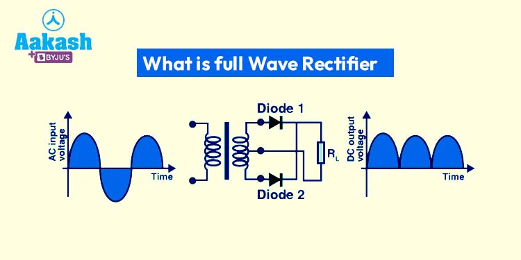
The center-tapped rectifier utilizes a center-tapped transformer to convert AC to DC. It consists of two diodes and a center-tapped secondary winding in the transformer. The center tap is grounded, and the two ends are connected to the diodes.
During the positive half-cycle of the AC input, one end of the transformer’s secondary winding becomes positive relative to the center tap, causing one diode to conduct and produce a positive voltage at the output. In the negative half-cycle, the polarity reverses, and the other diode conducts, still producing a positive voltage at the output. This results in a pulsating DC output, similar to the bridge rectifier.
Advantages of Full Wave Rectifiers:
Higher Efficiency: Full-wave rectifiers provide a higher average output voltage compared to half-wave rectifiers, making them more efficient.
Constant Output: The output of a full-wave rectifier has a lower ripple voltage compared to half-wave rectifiers, providing a more stable and smoother DC signal.
Utilization of AC Signal: Full wave rectifiers make efficient use of both the positive and negative halves of the AC signal, maximizing the usage of the input power.
Limitations of Full Wave Rectifiers:
Complexity: The bridge rectifier requires four diodes, and the center-tapped rectifier necessitates a center-tapped transformer, making the circuit more complex than a half-wave rectifier.
Higher Cost: Due to the additional components, full wave rectifiers tend to be slightly more expensive to implement.
In conclusion, the full wave rectifier is a fundamental circuit that plays a vital role in converting alternating current into direct current, making it suitable for a wide range of electronic applications. Its efficiency, constant output, and effective use of the AC signal make it a popular choice in various electronic devices and power supply systems.
Frequently Asked Questions (FAQs) About Full Wave Rectifiers:
1. What is a full wave rectifier, and how does it work?
A full wave rectifier is an electronic circuit used to convert alternating current (AC) into direct current (DC). It ensures that the output voltage remains positive, regardless of the polarity of the input AC voltage. It rectifies the AC signal into a pulsating DC signal by using diodes to allow current flow in one direction during both positive and negative half-cycles of the AC input.
2. What are the types of full wave rectifiers?
There are two main types of full wave rectifiers: the bridge rectifier and the center-tapped rectifier. The bridge rectifier uses four diodes arranged in a bridge configuration, while the center-tapped rectifier employs a center-tapped transformer and two diodes.
3. What are the advantages of using a full-wave rectifier over a half-wave rectifier?
Full-wave rectifiers have several advantages over half-wave rectifiers. They provide higher efficiency as they utilize both positive and negative halves of the AC signal, resulting in a higher average output voltage. Additionally, full wave rectifiers produce a smoother and more stable DC output due to their lower ripple voltage.
4. What is the difference between a bridge rectifier and a center-tapped rectifier?
The primary difference between the bridge rectifier and the center-tapped rectifier lies in their circuit configurations. The bridge rectifier uses four diodes in a bridge arrangement, while the center-tapped rectifier utilizes a center-tapped transformer and two diodes. Both types achieve the same goal of full wave rectification.
5. What are the limitations of full wave rectifiers?
Although full wave rectifiers offer several advantages, they do have some limitations. Firstly, their circuit complexity is higher than that of half-wave rectifiers, requiring more components. As a result, full-wave rectifiers tend to be slightly more expensive to implement. However, their benefits in terms of efficiency and output stability often outweigh these drawbacks, making them widely used in electronic applications.